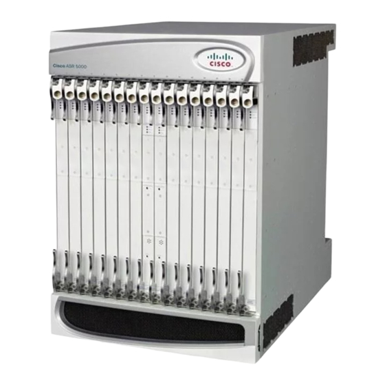
Cisco ASR 5000 Процедура установки - Страница 3
Просмотреть онлайн или скачать pdf Процедура установки для Шлюз Cisco ASR 5000. Cisco ASR 5000 8 страниц. Applying power and verifying the installation
Также для Cisco ASR 5000: Руководство по установке (18 страниц), Руководство по установке (33 страниц), Руководство по установке (37 страниц)

Installation Procedure Overview
Item
4
5
6
7
8
Installation at a Glance
The list below summarizes the installation process for the chassis.
Unpacking instructions are not provided in this document. Please refer to the Unpacking the ASR 5000
Note
Chassis document shipped with the system, for information and instructions on this topic. The chassis
and cards are shipped separately.
• Unpack the chassis and cards
• Determine which chassis mounting option to use: standard or mid-mount.
• Install the chassis into a standard 19-inch equipment rack or telecommunications cabinet.
• Connect the chassis to earth ground.
• Install application cards into the front of the chassis.
• Install line cards into the rear of the chassis.
• Connect data cables to the line cards.
• Connect power cables to the chassis.
• Apply power to the chassis.
• Verify that the installation was successful.
Once the installation has been validated, you will be directed to the System Administration Guide for instructions
on how to configure the system for operation.
Description
Upper bezel: Covers the upper fan tray bay.
Lower fan tray cover/EMI shield: Secures the lower fan tray assembly in place and serves as an
EMI shield. The cover also provides an air baffle allowing air to enter into the chassis.
Lower bezel: Covers the lower fan tray bay.
Lower fan tray assembly: Draws air into the chassis through the chassis' front and sides for cooling
and ventilation. It is equipped with a particulate air filter to prevent dust and debris from entering
the system.
Power Filter Units (PFUs): Each of the system's two 165 amp PFUs provides -48 VDC power to
the chassis and its associated cards. Each load-sharing PFU operates independently from the other
to ensure maximum power feed redundancy.
Installation at a Glance
ASR 5000 Installation Guide
3
