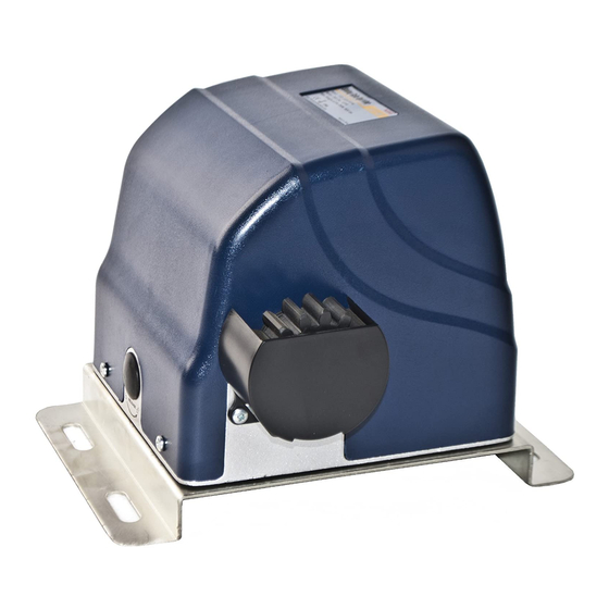
Aleko AR 900 Руководство пользователя - Страница 8
Просмотреть онлайн или скачать pdf Руководство пользователя для Открыватель ворот Aleko AR 900. Aleko AR 900 16 страниц. Sliding gate operator

* Before starting installation, ensure that there is no point of friction during the entire movement of
the gate and there is no danger of derailment.
* Ensure that the Warning Signs are present.
Necessary Tools: The following tools may be necessary to install the Gate operator. You will need
screwdrivers, an electric drill, wire cutters and a wire stripper, a socket set, and possibly access to a
welder.
When install the operator, you should build a concrete pad to support the base plate of operator in order to
maintain proper stability.
The installation proceeds are as follows:
1.Dig a hole for a concrete pad which
should be approximately 50 x 32 x
35cm (20 〞 x 13 〞 x 14 〞 ). It may
protrude 10 cm (4") above ground and
25 cm (10") in depth underground.
Increase the pad height if necessary to
protect the system from flooding, heavy
snow etc.
2. Prepare one or more conduits for the
electrical cables before pour concrete.
Remember that cable conduits have to
pass through the hole in the base plate.
3. Pour concrete and before it starts to
harden, check that it is parallel to the
gate leaf and perfectly level.
4. Mark the position of four expansion
anchors according to the position of
mounting hole on the base plate as
soon as concrete become harden.
Double check your marking, move the
base plate and drill the 4 holes using a
10mm (3/8") masonry bit. Put the 4
expansion anchors (provided) into the
holes and firmly tighten.
5. Place the opener onto base plate. Check that it is perfectly parallel to the gate leaf, and then screw the
four bolts and washers supplied. It's only temporary installation. Further adjustment will be required when
install the rack.
Manual Operation
The operator should be put in the manual (emergency release) position before fitting the rack, installing the
operator and limit switch. The process is as follows:
1) Take of the rubber stopple.
2) Insert the Release Key ( provided) and turn it in counter-clockwise 90° to disengage the clutch between the
gear shaft and power output. Now the operator is in the manual operation.
7
