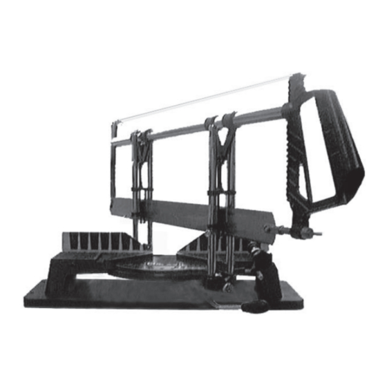
Clarke 6470057 Инструкции по сборке - Страница 2
Просмотреть онлайн или скачать pdf Инструкции по сборке для Пила Clarke 6470057. Clarke 6470057 2 страницы. Mitre saw

Thank you for purchasing this CLARKE Mitre Saw, which is designed for DIY, Hobby and
Professional users alike.
GUARANTEE
This CLARKE product is guaranteed against faulty manufacture for a period of 12 months
from the date of purchase. Please keep your receipt as proof of purchase.
This guarantee is invalid if the product is found to have been abused or tampered with in
any way, or not used for the purpose for which it was intended.
Faulty goods should be returned to their place of purchase, no product can be returned to
us without prior permission.
This guarantee does not effect your statutory rights.
COMPONENT GUIDE
Fig. 1
GROUP C - Pivot Pin, c/w 2 locating
screws (with pointed ends)
GROUP D - Four plastic feet c/w fixing
screws
GROUP E - Two Depth of Cut Stops -
locate on Guide Rods, one
at each end of thre carriage
GROUP F - Four Base fixing screws with
Hex. key
Not Shown - Base and Saw complete
Unpack and lay out all components,
identifying each one according to the
schedule below. Should any part br missing
or damaged, contact your Clarke dealer
immediately.
GROUP A - Length Stop Assembly, compr:
1. Two Rods - one long with threaded end,
one short.
2. Lock nut - screw on to end of long rod.
3. Plastic pad - fits on flat end of short rod.
4. Clamp assy c/w two clamping screws
GROUP B - Work Clamp Assembly, compr:
1. One short rod with threaded end.
2. Lock nut - screw on to end of short rod.
3. Adjuster Screw.
4. Plastic Pad - fits on end of Adjuster Screw.
5. Clamp Assembly complete with clamping
screw
ASSEMBLY
1. Mitre Table to Carriage
Attach the Carriage to the Mitre Table so that the
pointer locates over the ledge, at the side of the Mitre
Table, as shown in fig.2. It will be necessary to lift the
locking lever, to depress the locking mechanism, so
that the two components can be connected.
Line up the pivot hole in the Carriage with that in the
Mitre Table, and slide in the Pivot Pin from below as
shown in fig. 3. The pin is a tight fit in the Mitre table so
that i t will be necessary to turn the table over and
tap the pivot pin home with a light hammer as shown
in fig. 4.
With the pivot pin fully home, screw in the two
locating screws (see fig. 5). Screw them in equally, so
that the carriage is capable of moving evenly and
smoothly on the pivot pin without sloppyness.
2. Feet
Attach the feet to the base at the positions marked
on the underside, using the screws provided.
3. Base
Attach he base to the mitre table using the four hex.
socket screws provided.
4. Work Clamp
Screw the Clamp Support into one of the threaded
holes in the front face of the Mitre Table, (see fig. 6),
depending upon which side of the saw blade your
work is to be mounted, remembering NOT to clamp
the free end of the work.
Secure the Clamp Support with the nut provided
5. Work Stop
Screw the Stop Support rod into the threaded hole at
the end of the Mitre table and lock in place using the
nut provided.
6. Saw Blade
Slide a Depth of Cut Stop on to one of the Guide
Support Rods, (one at each end of the carriage),
before carefully sliding the Blade Guides on to the
Guide Rods. (The stops are secured to the guide rods
at any desired position, to limit the travel of the saw
blade).
Your Mitre Saw is now fully assembled and ready for
use.
Fig. 2
Fig. 3
Fig. 4
Fig. 5
Fig. 6
