Balmar Smartgauge Руководство по установке и эксплуатации - Страница 3
Просмотреть онлайн или скачать pdf Руководство по установке и эксплуатации для Измерительные приборы Balmar Smartgauge. Balmar Smartgauge 20 страниц. Battery monitor

PAGE 3
CAUTION & WARNING: This manual is written with the intention for use by a qualified electrical
technician. It does not identify normal practices or procedures that would be expected of a qualified
electrician. Please review and comply with any installation and/or safety standards, such as those
provided by ABYC or other agencies regulating electrical system safety. Please review the instruction
manuals for any equipment or tools that you may be using to complete this installation.
CAUTION: Please fully review this manual before commencing installation.
Certificate of Conformity:
Declaration of Conformity
Smartgauge™ is in compliance with the requirements of EU Electromagnetic Compatibility (EMC)
Directive 89/336/EEC. Smartgauge™ complies with RoHS (Reduction of Hazardous Substances)
Directive 2002/95/EC. Smartgauge™ contains no Lead. At the end of life, Smartgauge™ should be
disposed of as normal electrical waste.
SECTION 2.0 – QUICK START GUIDE
CAUTION & WARNING:
Batteries are hazardous
items. Please follow bat-
tery manufacturer's rec-
ommendations for health
and safety. Use only the
appropriate tools in con-
junction
with
manufac-
turer's instructions. Isolate
both battery and AC power
supplies before attempting
installation.
CAUTION & WARNING:
The Quick Start Guide
does not refer to each and
every Caution & Warning
Statement in this man-
ual. Be sure to observe
safe
working
practices
at all times. Refer to the
full manual if you are un-
sure of any practices that
may damage the Smart-
gauge™ unit, your system
wiring or health.
The Quick Start section of this guide assumes Smartgauge™ is being installed
for the first time. If this is not the case, please refer to the main section of this
manual as the power up sequence will be different.
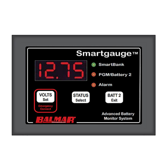
The Smartgauge™ display panel is typically mounted at the dash or navigation
area, or in other locations where it can be easily accessed for viewing. The rect-
angular display panel requires a rough opening measuring 3.75" wide by 2.55" tall,
as illustrated in Diagram 1. The overall dimensions are 4.40" wide by 3.00" tall. The
panel depth is 1". Access to the rear of the monitor is necessary for the installation
of ground and positive sense wires from the monitor directly to the battery banks. In
addition, there are terminals for wiring connections to install separate wires for an
audible or visual low-voltage/low-battery capacity alarm. Four cutout dimples can be
found on the back of the mounting flange of the monitor's display if mounting screws
are desired.
Once a location has been determined for the monitor panel, sensing and ground
wires can be run to the batteries, as described in Diagram 2 on the following page.
SECTION 1.0 – INTRODUCTION
Diagram 1
