DIYRE G BUS Руководство по эксплуатации - Страница 4
Просмотреть онлайн или скачать pdf Руководство по эксплуатации для Воздушный компрессор DIYRE G BUS. DIYRE G BUS 13 страниц. Stereo vca compressor

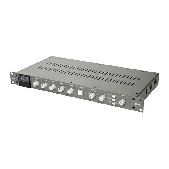
Front Panel Description
THRESHOLD
: Sets the gain level at which compression starts. The clockwise position is maximum (least sensitive),
turn counterclockwise to lower the threshold.
ATTACK
: Sets the attack time of the compressor, measured in milliseconds.
RATIO
: Sets the ratio of the compression between 2:1, 4:1, and 10:1 (depending on calibration).
RELEASE
: Sets the release time of the compressor, measured in seconds.
: Adds gain to make up for that lost when compressing. Counterclockwise is unity gain.
MAKE-UP
COMPRESSOR
: Engages compression. In the
compressor, including the
FILTER
: Engages the sidechain filters or external sidechain input. In position 1 (counterclockwise) the filters are
and have no effect on the signal. Positions 2-4 are high-pass filters, with the corner frequencies indicated
OFF
in hertz. Position 5 is a shelf filter that deemphasizes low frequencies and emphasizes high. Position 6 is for the
external sidechain input.
DRY/WET
: Blends the dry signal with the compressed signal when
: Engages the
MIX
DRY/WET
disabled and has no effect.
: Sums the left and right signals at the start of the sidechain detection circuit. The default,
MONO SC
position is how the original console worked.
XFMR
: Switches between a clean, IC-based output and a saturated transformer output. The default,
position is closest to the original.
DRIVE
: Switches between three drive settings. These increase the gain going to the transformer and attenuate
after it to maintain unity gain while increasing saturation.
2
OUT
stage if it is engaged.
XFMR
control for parallel compression. In the
position the signal still runs through the audio path of the
MIX
is engaged.
position the mix circuitry is completely
OUT
,
OUT
OUT
,
