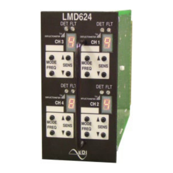
EDI LMD Series Руководство по эксплуатации - Страница 10
Просмотреть онлайн или скачать pdf Руководство по эксплуатации для Датчики безопасности EDI LMD Series. EDI LMD Series 15 страниц. Deflectometer, inductive loop monitor
Также для EDI LMD Series: Руководство по эксплуатации (15 страниц)

2.6.1 CURRENT FAULT
If a fault is detected, both the DET (Red) and FLT (Yellow) LEDs continuously emit a
sequence of flashes and the DEFLECTOMETER will display the letter "F". Each type of
fault is identified by a different flash sequence followed by a one second pause:
Flash Sequence
1 flash
2 flashes
3 flashes
2.6.2 PREVIOUS FAULT
If the fault condition is removed, the DET indicator and the channel output will return to
normal operation. The FLT indicator will continue to flash indicating that a fault had
previously occurred. This Previous Fault indication may be reset by momentarily pressing
the MODE and FREQ buttons simultaneously. See section 2.5.2.
2.6.3 CHANNEL STATUS REPORTING
The LMD Series Loop Monitor will also report the current channel status on the solid state
outputs, Channel 1 Status Output and Channel 2 Status Output. The outputs provide for
five different status conditions:
Condition
Normal Operation
Detector Unit Failure
Open Loop
Shorted Loop
Excessive Inductance Change
The Channel Status Outputs reflect the current fault status of the unit for each channel. The
LMD Series will report the "Normal Operation" state when a channel is set to the OFF
operational mode. Consult the factory for other options.
2.7 LMD624H DISPLAY SELECT CONTROL
The LMD624H half width model provides four channel operation, but only displays
DEFLECTOMETER information for two selected channels at a time. A two position toggle
switch on the front panel selects the mode of the front panel buttons and
DEFELCTOMETER display to be either channels 1 and 2, or channels 3 and 4.
The LED indicators for the Detect (DET) and Fault (FLT) indicators are provided for all four
channels and are always enabled regardless of the channel selected for the
DEFELCTOMETER display.
Eberle Design Inc.
LMD622 and LMD624 Series
Operations Manual
Open Circuit Loop (or Inductance too high)
Shorted Circuit Loop (or inductance too low)
>25% Change in Inductance
Continuous False (high)
50 ms True / 50 ms False
100 ms True / 50 ms False
150 ms True / 50 ms False
Fault
Status Output
Continuous True (low)
Page 7
