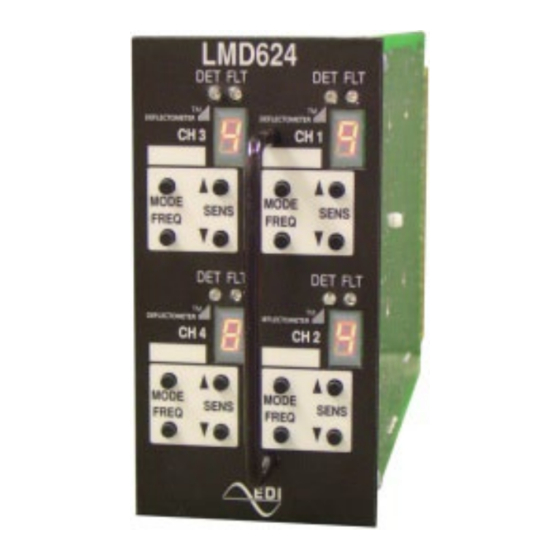
EDI LMD Series Руководство по эксплуатации - Страница 9
Просмотреть онлайн или скачать pdf Руководство по эксплуатации для Датчики безопасности EDI LMD Series. EDI LMD Series 15 страниц. Deflectometer, inductive loop monitor
Также для EDI LMD Series: Руководство по эксплуатации (15 страниц)

LMD622 and LMD624 Series
Operations Manual
2.4.2.1 EXTEND ALWAYS (DEFAULT)
Call Extend time starts counting down when the last vehicle clears the loop detection zone.
During the Extend time the DET indicator will flash four times per second and the
DEFLECTOMETER will display the letter "E". Any vehicle entering the loop detection zone
during the Extend time period causes the Extend timer to be reset and the output
maintained. The Timer Control input has no effect on this mode.
2.4.2.2 EXTEND ON GREEN (EOG)
Call Extend time starts counting down when the last vehicle clears the loop detection zone
if the Timer Control input is True (low). During the Extend time the DET indicator will flash
four times per second and the DEFLECTOMETER will display the letter "E". Any vehicle
entering the loop detection zone during the Extend time period causes the Extend timer to
be reset and the output maintained.
The Extend on Green mode is enabled by a factory installed diode located at E6 on the
pcb. Consult the factory for details.
2.4.3 TIMER CONTROL INPUTS
Timer Control inputs are provided for each channel to modify the operation of the Delay
and Extend Timing functions. The application of a True (low) state voltage will inhibit the
Delay timing function and/or enable the Extend timing function as described in sections
2.4.1 and 2.4.2.2. When the Timer Control Input is True (low) the decimal point of the
channel DEFLECTOMETER display will illuminate.
Timer Control inputs are primarily provided for backward compatibility.
2.5 MISCELLANEOUS
2.5.1 CHANNEL OFF
If a channel is not to be used, it may be switched off (disabled) by setting the Operational
Mode to OFF. See section 2.2.6.
2.5.2 RETUNE OR RESET A CHANNEL
Press the MODE and FREQ buttons simultaneously to reset the channel. This will clear any
previous loop fault indication and cause the channel to retune.
2.5.3 FACTORY DEFAULT SETTINGS
Press the Channel 1 MODE and FREQ buttons simultaneously while first applying power to
the unit to reset all channels to the factory default settings.
Factory Defaults
Sensitivity Level
6
Operational Mode
Short Presence
Frequency Level
High
2.6 LOOP FAULT MONITORING
The LMD Series Loop Monitor continuously checks the integrity of the loop. The system is
able to detect open circuit loops, shorted loops, or sudden changes in inductance
exceeding 25% of the nominal inductance.
Eberle Design Inc.
Page 6
