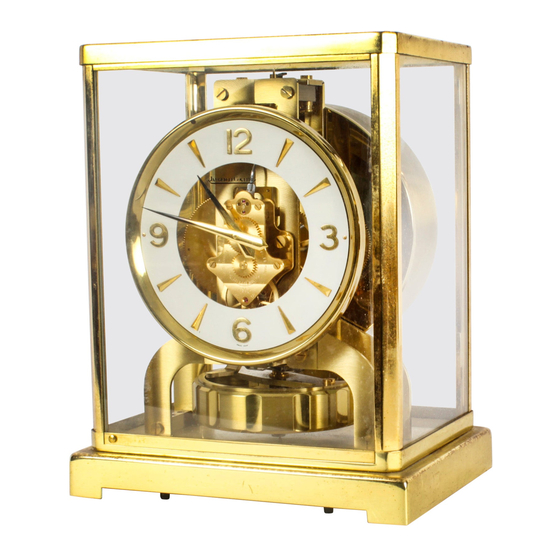
ClockWorks Press ATMOS Руководство - Страница 8
Просмотреть онлайн или скачать pdf Руководство для Часы ClockWorks Press ATMOS. ClockWorks Press ATMOS 10 страниц. The perpetual motion clock

To replace the wire inside the balance tube, use Tool
No. 3 (Figure 5). When the balance roller unit has been
remounted, suspend it on the framework. To do this, use Tool
No. 1 to push the wire inside the upper bridge and use Tool
No. 8 (ring) to raise the balance. Use pliers to draw the end of
the wire until banking stem M (Figure 1) lies under lower
bridge P. Insert suspension-wire pin N (Figure 3), press it
down while stretching the wire, give a light blow on the pin
in order to make wire slip and release banking stem from
lower bridge. The lower bridge P (Figure 1) must divide the
space between the two planes of banking stem M equally, the
regulating clamp must be tightened and make sure that the
wire is suspended in the center of the tube. There must be no
twisting or torsion of the wire between the point where it is
attached to the wire sleeve by the pin and the point where it
lies inside the threaded clamp.
Check whether the balance is poised and engages the
escapement. For poising see Page 7. The balance engages
when the impulse pin lies forward while the balance is dead
centre. If this is not the case, turn roller through disk O (Figure
3), after having released the screw of said disk O. Then count
oscillations of balance for 15 minutes. If variation exceeds 1
second, more or less, per 15 minutes, adjust the balance by
adding or lessening oscillating and regulating weights.
1 mm of oscillating weight = 8 seconds per 15 minutes.
1 mm of regulating weight = 4 seconds per 15 minutes.
The two sets of oscillating and regulating weights can be
compared on a very sensitive pair of scales, so that, when set
in place on the balance wheel itself, the latter will not be put
out of poise. As soon as sufficiently accurate timing has been
obtained by adjustment of these sets of weights, the final rating
12
can be obtained by regulator R (Figures 3 and 6) which allows
for exact determination of the required adjustment:
1 division = 10 seconds per 24 hours
If variation exceeds 50 seconds per 24 hours, adjust for
50 seconds when the regulator is in the middle of its run, by
displacing the latter to left or right; then lock regulator tube
V (Figure 6) with appropriate Tool No. 10 (Figure 5) and pull
regulator in opposite direction (it will turn without modifying
adjustment) and finish adjusting after having freed the
regulator tube.
Then replace base plate and check for good operation of
balance locking mechanism.
Should the movement require overhauling (use Tool No.
7-Movement Holder) we wish to stress that, owing to the
minimum power which is transmitted and the slow movement
mechanism, all wheels and pinions must be cleaned, (not
lubricated) and run perfectly free. The surfaces of rest and
impulse of all runners must be perfectly polished, the pallets
very clean and the locks slight with only a small back lash.
Carefully observe poise of the fork which is suspended
by the two pivots of the pallet staff (like a watch balance on
the poising tool); the fork must be slightly heavier on the
horn side, to secure one complete oscillation per minute. At
rest, the fork must have a perfectly vertical position on the
tool; if not, correct by adding a counterweight as required.
(This slight fault in poise is important for it may prevent good
timing.)
When the movement is remounted, put it back and also
check the good operation of the escapement and the fork. If
13
