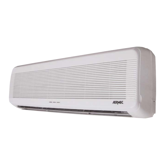
AERMEC FCW Series Буклет по установке - Страница 8
Просмотреть онлайн или скачать pdf Буклет по установке для Нагреватель AERMEC FCW Series. AERMEC FCW Series 19 страниц. Fan coil

tale che l'aria possa essere distribuita in tutta la stanza, che
non vi siano ostacoli (tende o oggetti) al passaggio dell'aria
dalle griglie di aspirazione (fig. 2). L'unità deve essere dispo-
sta in modo da facilitare la manutenzione ordinaria (pulizia
del filtro) e straordinaria, nonchè l'accesso alla valvola di
sfiato dell'aria sulla batteria di scambio termico, ad una
altezza di 190 ÷ 220 cm.
L'unità deve essere collegata direttamente ad un attacco elet-
trico o ad un circuito indipendente.
Per proteggere l'unità contro i cortocircuiti, montare sulla
linea di alimentazione un interruttore onnipolare magnetoter-
mico max. 2A 250V (IG) con distanza minima di apertura dei
contatti di 3mm.
Il cavo elettrico di alimentazione deve essere del tipo
H07 V-K oppure N07 V-K con isolamento 450/750V se
incassato in tubo o canaletta. Per installazioni con cavo in
vista usare cavi con doppio isolamento di tipo H5vv-F.
Per tutti i collegamenti seguire gli schemi elettrici a corredo
dell'apparecchio e riportati sulla presente documentazione
(fig. 11-12).
Gli attacchi idraulici dell'unità FCW sono Femmina Ø
1/2"G; l'attacco dello scarico condensa ha un diametro
esterno Øe 16 mm.
Le tubazioni di andata e ritorno devono essere uguali, in
rame, con diametro minimo Ø 1/2", adeguatamente isolate
per evitare dispersioni termiche e gocciolamenti durante il
funzionamento in raffreddamento.
E' necessario che le condutture dell'acqua, dello scarico
condensa e il circuito elettrico sulla parete siano già stati
previsti. Il diametro del foro di passaggio per i collegamenti
deve avere un diametro minimo di 65 mm e le tubazioni
posizionate in modo da mantenere lungo il percorso un'ade-
guata pendenza (min.1%), tale da assicurare l'evacuazione
della condensa prodotta nel funzionamento a freddo del
ventilconvettore.
La rete di scarico della condensa deve essere opportunamen-
te dimensionata, qualora lo scarico condensa sia collegato
alla rete fognaria, per evitare ingresso di odori sgradevoli, si
consiglia di effettuare un sifone (fig. 9).
Il foro di servizio delle condutture può essere posizionato
sia alla destra che alla sinistra dell' unità (figg. 3-4).
La parete di appoggio deve essere robusta e non soggetta a
vibrazioni.
Non installare l'unità vicino a fonti di calore, vapore o gas
infiammabile.
Non installare in luogo esposto alla luce solare diretta.
INSTALLAZIONE
Prima dell'installazione accertarsi che le impostazioni del
ventilconvettore corrispondano alle esigenze dell'impianto,
in caso contrario modificare le impostazioni dei Dip Switch
posti sulla scheda elettronica (fig.15-16)
Nei ventilconvettori FCW40 la dima (pannello a muro) è fis-
sata con 4 viti, prima di procedere all'installazione dell'uni-
A
base del pannello
bas du panneau
Seite herausziehen
8
B
2
1
panel base
routine maintenance (filter cleaning) and special maintenan-
ce. Access must also be left free to the air bleed valve on the
heat exchanger coil at a height of 190 -220 cm.
The unit must be connected directly to a power supply
socket or independent circuit.
To protect fan coils against short circuits, always fit the
power cable to the units with 2A 250V (IG) thermo-magne-
tic all-pole switches with a minimum contact gap of 3 mm.
The power supply cable must be rated H07 V-K or N07 V-K
with 450/750V insulation class if embedded in pipe or
cable raceways. For installation with cable in sight use dou-
ble insulation H5vv-F type.
For all connections refer to the wiring diagrams supplied with
the appliance and specified in this documentation (fig. 11-12).
Water connections on the FCW unit are female Ø 1/2"G
fittings; the external diameter of the condensate drain con-
nector is Ø 16 mm.
Delivery and return lines must be copper and the same size
with a minimum diameter of Ø 1/2", suitably insulated to pre-
vent heat loss and dripping during operation in cooling mode.
The water, condensate drain and electrical circuit lines in
walls must be laid prior to appliance installation. The mini-
mum diameter of the through-hole for connections is 65
mm and pipelines must be laid to ensure sufficient gradient
(min.1%), throughout the route to ensure drainage of the
condensate formed during fancoil cooling operation mode.
The condensate drain line must be suitably sized; when
connected to a sewage mains the installation of a siphon is
recommended to avoid detection of unpleasant odours (fig. 9).
The cable service outlet can be positioned to the right or left
of the unit (fig. 3-4).
The support wall must be stable and not subject to vibra-
tions.
Never install the appliance in the vicinity of heat sources,
vapour or flammable gases.
Never install the appliance in an area exposed to direct sun-
light.
INSTALLATION
Before installing the unit, be sure that all settings of fan coil
correspond to the system requirements. Otherwise change
Dip Switch settings placed on the electronic board.(fig
15-16).
For the FCW40 fan coils, the dima (wall hook board) is faste-
ned with 4 screws; before proceding with the installation of the
unit it must be removed, according to the following procedure:
- To pull one side of base case B and take it off
(To pull as the arrow direction showed figure 5- ①).
- To pull the other side of base case B and take it off
(To pull as the arrow direction showed figure 5- ②)
- To loosen cross screw from base case A and take it off
(Figure 5- ③).
- To loosen inside stopper, pull the right side of base case A
forward and slide base case A toward left side, so can
relase two fixed hooks (Figure 5- ④)
A
5
gancio
hook
crochet
Haken
tappo
stopper
bouchon
Stopper
4
fig. 5
3
