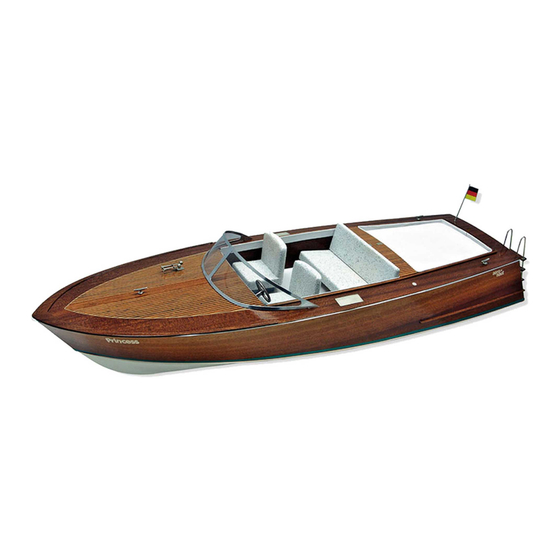
aero-naut Princess Talimatlar Kılavuzu - Sayfa 2
Oyuncak aero-naut Princess için çevrimiçi göz atın veya pdf Talimatlar Kılavuzu indirin. aero-naut Princess 17 sayfaları. 3081/00

Introduction:
The model should be assembled following the sequence of the stages of construction described in these instructions. Each subsequent stage then
shows the previous sub-assembly or procedure in completed form.
The laser-cut components are individually numbered. The manufacturing method leaves small tabs on some parts which have to be cut away using a
thin-bladed modelling knife. The dark edges of the laser-cut parts should also be rubbed off using abrasive paper in order to obtain sound glued
joints. Check that all components fit accurately before reaching for the glue, and carry out any minor trimming required. Allow all glued joints to dry
out fully before starting the next stage of construction. We recommend a fast-setting waterproof white glue for all joints involving the wooden
structure; please take care to prevent adhesive running onto the untreated mahogany parts and any external surfaces which will be visible on the
finished model, as the glue will show up through the final painted finish. We recommend that you apply a coat of sanding sealer (Order No.
7666/02) to the mahogany components before gluing. The whole of the boat - inside and out - must be given several coats of clear water-resistant
boat lacquer before the model is placed in the water, as this waterproofs the wood and the glued joints. If you have to glue parts to areas which
have already been lacquered, use two-pack adhesive for those joints.
Power system:
Race 650, Order No. 7124/18, with seven Sub-C cells or 2S LiPo, three-bladed 40 mm Ø propeller, M4, Order No. 7160/06
actro C5, Order No. 7002/35, with ten Sub-C cells or 3S LiPo, three-bladed 50 mm Ø propeller, M4, Order No. 7160/10
Speed 700, approx.1500 KV (rpm / V), with ten Sub-C cells or 3S LiPo, three-bladed 50 mm Ø propeller, M4, Order No. 7160/10
15
10
0
11
12
0
11
2.1
2
5
6
7
8
9
5
6
7
8
9
aero-naut Modellbau GmbH & Co. KG, Stuttgarter Str. 18, D-72762 Reutlingen
We recommend our aero-pick modelling pins, Order No.
7855/02, for use throughout construction.
1
Glue the frames 2 + 2.1 together with the edges flush.
1
2+2.1
3
4
Insert the frames 1 - 11 and the brace 15 in the
2
slots in the jig 0. Frame 7 is prepared as standard
to suit an actro C or 650-size motor. If you intend
to fit a larger motor, you will need to modify frame
7 to suit.
3
Carefully insert the keel 12 in the notches in
frames 5 - 9, 11 and in the jig 0 at the bow; note
that the keel 12 must end flush with the top of
the frames. Frame 7 supports the motor (see
Stage 22), and therefore must be fitted at an
angle.
