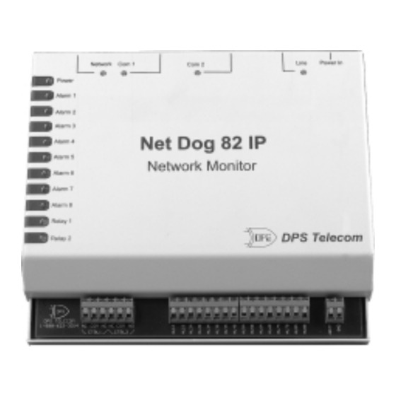
DPS Telecom Net Dog 82 IP Kullanım Kılavuzu - Sayfa 3
Ağ Donanımı DPS Telecom Net Dog 82 IP için çevrimiçi göz atın veya pdf Kullanım Kılavuzu indirin. DPS Telecom Net Dog 82 IP 12 sayfaları.

Vcc
A = Pins 1, 2 jumpered
B = Pins 2, 3 jumpered
3
C = Pins 3, 4 jumpered
D = Pins 4, 5 jumpered
F
E = Pins 1, 2 jumpered
F = Pins 2, 3 jumpered
Fig. 3 -Alarm inputs can be configured
with jumpers A through F.
AL 1A
AL 1B
- Batt.
AL 1A
AL 1B
Contact to Ground (jumpers A + C)
- Batt.
AL 1A
AL 1B
Vcc
TTL Internally Biased (jumpers B + D + F)
AL 1A
AL 1B
TTL Externally Biased (jumpers B + E)
Fig. 4 - Each alarm input has
four configuration options.
D-PC-295-10A-0V
May 5, 2000
- Batt.
1
A
2
B
3
C
4
D
5
B Term.
2
1
E
Default
Dry Contact (jumpers A + C)
Default
Vcc
E
F
(J10) (J11) (J26) (J27) (J28) (J29) (J30) (J31)
A Term.
1
A
2
B
3
C
4
D
5
Alarm 1
(J5) (J12) (J13) (J14) (J24) (J25) (J22) (J23)
Fig. 5 - Circuit board jumper designations, located in
the lower right area of the circuit board.
Control Point Detail
Fig. 6 - Alarm and control points are easily
connected to the screw-lug terminals.
Power jack
for AC Adapter
Phone line
connection
RJ-12
COM 1- ASCII device and
configuration port - Female DB9
GND
5 4 3 2 1
9 8 7 6
Fig. 7 - Communication ports are located
on the back of the Net Dog.
3
1
1
1
1
1
1
2
2
2
2
2
2
3
3
3
3
3
3
1
1
1
1
1
2
2
2
2
2
3
3
3
3
3
4
4
4
4
4
5
5
5
5
5
6
2
3
4
5
7
Alarm Point 1
Alarm Point 1
(AL1A)
Return (AL1B)
Alarm Point Detail
COM 2 -
No function
Ethernet
Connection
RJ-45
6
5
4 Ring
3 Tip
2
1
RX
PIN #
SIGNAL DESCRIPTION
TX
1
NC
Not Connected
2
TX
Tranmsit Data
3
RX
Receive Data
4
NC
Not Connected
5
GND
Ground
6
NC
Not Connected
7
NC
Not Connected
8
NC
Not Connected
9
NC
Not Connected
1
1
E
2
2
F
3
3
1
1
A
2
2
B
3
3
C
4
4
D
5
5
8
Alternate Power
Connection
(-24 or -48VDC)
Power Detail
10
9
8
7
6 Receive In - (RI-)
5
4
3 Receive In + (RI+)
2 Transmit Out - (TO-)
1 Transmit Out + (TO+)
OG113939.001
