Draper Ropewalker Talimatlar Kurulum ve Çalıştırma - Sayfa 3
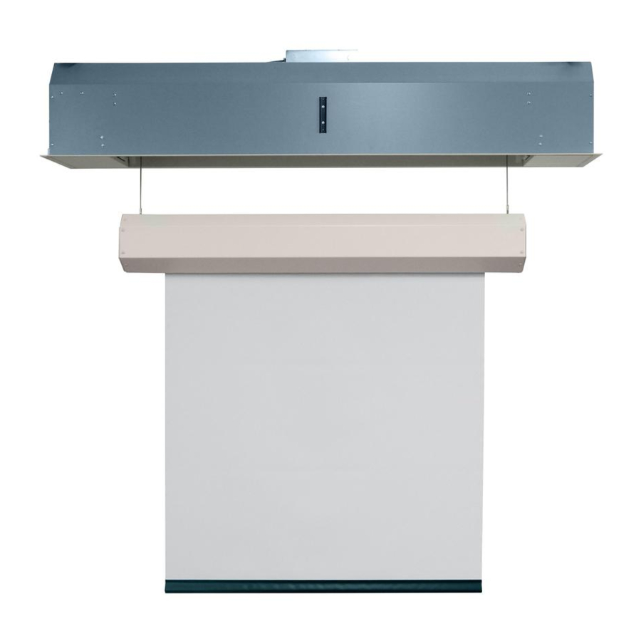
Projeksiyon Perdesi Draper Ropewalker için çevrimiçi göz atın veya pdf Talimatlar Kurulum ve Çalıştırma indirin. Draper Ropewalker 8 sayfaları. Electric projection screen with cable drop

Ropewalker
Section 2 - Mounting Ropewalker to Building Structure
Threaded Rod
Please Note: It is recommended that heavy items be hoisted up to the work area using appropriate machinery, i.e. hoisting lifts, block and tackle, etc.
When locating viewing surface and checking clearance for screen operation, remember surface is centered in the length of the case.
Regardless of mounting method used, the following points apply:
1. Screen should be lifted into position ONLY by end mounting brackets
or hoisting brackets. Keep case level by lifting both end plates at the
same time to prevent surface damage. Using more than one mounting
hole in each end plate ensures a much more stable installation. NEVER
attempt to lift screen along its length or in the middle.
2. Entire weight of unit MUST BE supported by end plates during
installation.
Please Note: DO NOT lift case at the center. Case leveling brackets
are ONLY used to reduce visible case deflection. Lift screen ONLY by
hoisting brackets. To ensure a safe installation, the entire weight of the
installed unit MUST BE supported by the mounting brackets.
Hoisting
Bracket
Section 3 - Electrical Connections
Screen operates on 110-120V, 60 Hz., 7.5A; or 220-240V, 50 Hz., 3A current draw.
Junction box is just above the bottom access panel at the left end of screen lift.
Figure 2
To access to the junction box
1. Open left side access panel by removing two
2. Remove two
5/16"
(2)
(8mm)
to expose red, brown, black, and white pigtail leads and green ground wire
(see Sec. 5, Ropewalker Wiring)
3. For optional low-voltage control, see Section 11.
4. Screen lift is shipped with internal wiring complete and control switch
boxed. Wire to connect screen to switch
should be furnished by installer. Connections should be made in accordance
with attached wiring diagram, and wiring should comply with national and
local electrical codes.
CAUTION: All operating switches should be "off" before connecting power.
(by others)
Figure 1
"-16
Threaded Rod
(10mm)
(use for adjusting deflection in extremely long units)
Hoisting
Hoisting
Bracket
Bracket
JUNCTION
BOX
screws from side of case
(2)
hex head screws that secure cover to junction box
.
and switch
to power supply
(es)
(es)
3. Screen should be positively and securely supported so that vibration or abusive
pulling will not weaken installation.
4. Installer must ensure that fasteners used are of adequate strength and suitable
for mounting surface. Installer must also ensure that structure is of adequate
strength. Supporting hardware
5. Entire bottom of case must be readily accessible after installation is complete.
6. Front, back, and top of case must be straight — not forced to warp or bow.
7. Do not use case to support adjacent sections of ceiling.
8. Do not seal unit in ceiling until electrical connections have been made and screen
has been operated successfully.
(by others)
Mounting Brackets attached
to Threaded Rod
Case Leveling Bracket
Case Support Brackets
NOT for use in supporting weight of case.
Section 4 - Removing Shipping Bracket
1. Remove the electrical access panel
2. Remove the shipping bracket from the shaft. Discard
Figure 3-A
.
(Fig 2)
Figure 3-B
fully
(es)
(chains, cables, rods, etc.)
"-16
(10mm)
(use for adjusting deflection in extremely long units)
(by others)
shipping bracket
RED
(shown in
with hangtag, Fig. 3-A)
NOT for use i
page 3 of 8
Mounting
must be essentially vertical.
to Threa
Threaded Rod
(by others)
Hoisting
Hoisting
Bracket
Bracket
Case
and locate the
(Section 3)
.
.
(Fig. 3-B)
SHIPPING
BRACKET
Case
