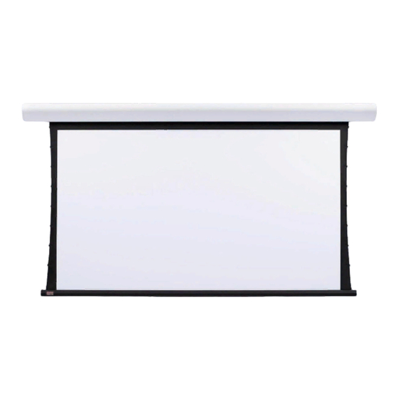
Draper Silhouette/Series E Kurulum ve Kullanım Talimatları
Projeksiyon Perdesi Draper Silhouette/Series E için çevrimiçi göz atın veya pdf Kurulum ve Kullanım Talimatları indirin. Draper Silhouette/Series E 5 sayfaları. Electric projection screen
Ayrıca Draper Silhouette/Series E için: Kurulum ve Kullanım Talimatları (5 sayfalar)

220V Silhouette/Series E & V Electric Projection Screen by Draper
1 Read instructions through completely before proceeding; keep them for
future reference. Follow instructions carefully. Installation contrary to
instructions invalidates warranty. Care in mounting and correct operation
will mean long and satisfactory service from your Draper screen.
2 Screen should be accessible for complete removal should fabric become
damaged or should other service be required.
3 Screen should be installed level (using a carpenter's level).
4 Nothing should be fastened to screen dowel or viewing surface.
5 Operating switch(es) packed separately in screen carton. Do not discard
with packing material.
6 Screen operates on 220V AC, 50 hz., 1 ph. current.
NOTE: Screen has been thoroughly inspected and tested at factory and
found to be operating properly prior to shipment.
These instructions are meant as a guide only. They do not imply any
responsibility on the part of Draper, Inc. for improper installation or faulty
workmanship at the jobsite.
Installation
Your Draper screen can be mounted on a wall or suspended from the ceiling,
or mounted on 15cm or 25-36cm extension brackets. Extension brackets must
be ordered separately from Draper. With each method of installation, the case
must be mounted level and with the flat back parallel to the wall.
To reduce the risk of personal injury, use only the hardware which comes with
the screen or is specified in these instructions.
The screen (or extension brackets) should be mounted into studs or blocking
in the wall/ceiling, or in drywall (minimum thickness 13 mm [
fied anchors. For any other type of installation, follow all local building and
safety codes.
Steel studs, concrete or cinder block walls and all other types of non-wood
frame construction require the use of special screws or anchors. The selection
of appropriate mounting hardware should be made by a qualified professional
installer.
When locating viewing surface and checking clearance for screen's operation,
remember surface is centered in case.
Take care to install wall/ceiling electrical box and conduit so they will be fully
concealed by the screen case after installation.
Handle case carefully to avoid scratching.
Regardless of mounting method, screen should be positively and securely
supported so that vibration or even abusive pulling on the viewing surface will
not cause case to work loose or fall. Installer must insure that fasteners used
are of adequate strength and suitable for the mounting surface chosen.
Wall Mounting
Mount two, three or four aluminum brackets provided ("Z" Clips) on the wall
at desired height, using appropriate fasteners. Verify that they are in line and
level to fully engage with the mounting lip on back of screen case. 42 mm of
free space is required above the "Z" Clips to allow case lip to be engaged over
the lip of the "Z" Clips.
Engage the lip on back of screen case with lip of "Z" Clip and gently pull down
to fully engage case to brackets.
Copyright © 2014 Draper Inc.
Form SilhouetteE&V220V_Inst14-R
Installation/Operating Instructions
Caution
/
"]) with speci-
1
2
Printed in U.S.A.
Lip on back of case
"Z" Clip
(wall mounting bracket
supplied with Silhouette)
Ceiling/Suspended Mounting
Locate two offset ceiling brackets (supplied) and slide these into the chan-
nel on top of screen case by aligning the chamfered edges of each bracket
parallel to the channel length. Allow bracket to drop against bottom of channel
and then rotate bracket counter-clockwise. Slide one bracket to each end of
screen case until it stops against end cap of case. Tighten two set screws
to lock bracket in place. Make sure that the flange of the ceiling bracket that
has four holes is extended beyond the end caps of the case. Repeat above
procedure for second ceiling bracket, making sure to slide it towards opposite
end of case.
To mount against ceiling, hold screen case against ceiling and mark mount-
ing hole locations. Each bracket has two holes towards the front edge and
two holes towards the back edge. Installer must use at least two fasteners
per bracket with one fastener in one of the two holes closest to back edge
of bracket, and one fastener in one of the two holes closest to front edge of
bracket. Installer must insure that fasteners are of adequate strength and suit-
able for the mounting surface chosen.
(front of Silhouette case)
To mount suspended from ceiling, the brackets need to be installed on
screen case as noted on page one. Attach "S" Hooks (supplied) through the
holes in the brackets. Select the set of holes that allows the screen to hang
in a vertical position. The installer is to provide the materials and fasteners
to attach the "S" Hooks to the ceiling. Installer must insure that the fasteners
and suspension material is of adequate strength and suitable for the mounting
surface chosen.
If you encounter any difficulties installing or servicing your Silhouette screen, call your dealer or
Draper, Inc. Spiceland, Indiana, U.S.A., telephone (765) 987-7999 or fax (765) 987-1689.
US Patent Nos. 5,296,964; 6,111,694
Silhouette fully engaged
on "Z" Clip
Ceiling bracket in
channel of case
Ceiling bracket
Mounting fasteners
(supplied by others, 2 per bracket)
(right end of Silhouette case)
