Bosch 800 Series Kurulum Talimatları Kılavuzu - Sayfa 10

Fırın Bosch 800 Series için çevrimiçi göz atın veya pdf Kurulum Talimatları Kılavuzu indirin. Bosch 800 Series 40 sayfaları. Built-in wall ovens
Ayrıca Bosch 800 Series için: Kurulum Talimatları Kılavuzu (24 sayfalar), Kurulum Kılavuzu (40 sayfalar), Kullanım ve Bakım Kılavuzu (12 sayfalar), Kurulum Kılavuzu (23 sayfalar), Kurulum Kılavuzu (28 sayfalar), Kurulum Kılavuzu (32 sayfalar), Kullanım Kılavuzu (32 sayfalar), Kurulum Kılavuzu (32 sayfalar), Hızlı Başlangıç ve Güvenlik Kılavuzu (7 sayfalar), Kullanım ve Bakım Kılavuzu (40 sayfalar), Kurulum Kılavuzu (40 sayfalar), Kurulum Kılavuzu (32 sayfalar), Kurulum Kılavuzu (48 sayfalar), Kullanım ve Bakım Kılavuzu (33 sayfalar), Kullanım ve Bakım Kılavuzu (49 sayfalar), Hızlı Başlangıç Kılavuzu (7 sayfalar), Hızlı Başlangıç ve Güvenlik Kılavuzu (13 sayfalar), Kurulum Kılavuzu (32 sayfalar), Servis Kılavuzu (36 sayfalar), Kurulum Talimatları Kılavuzu (29 sayfalar), Kullanım ve Bakım Kılavuzu (24 sayfalar), Kullanım ve Bakım Kılavuzu (40 sayfalar), Kurulum Talimatları Kılavuzu (28 sayfalar)
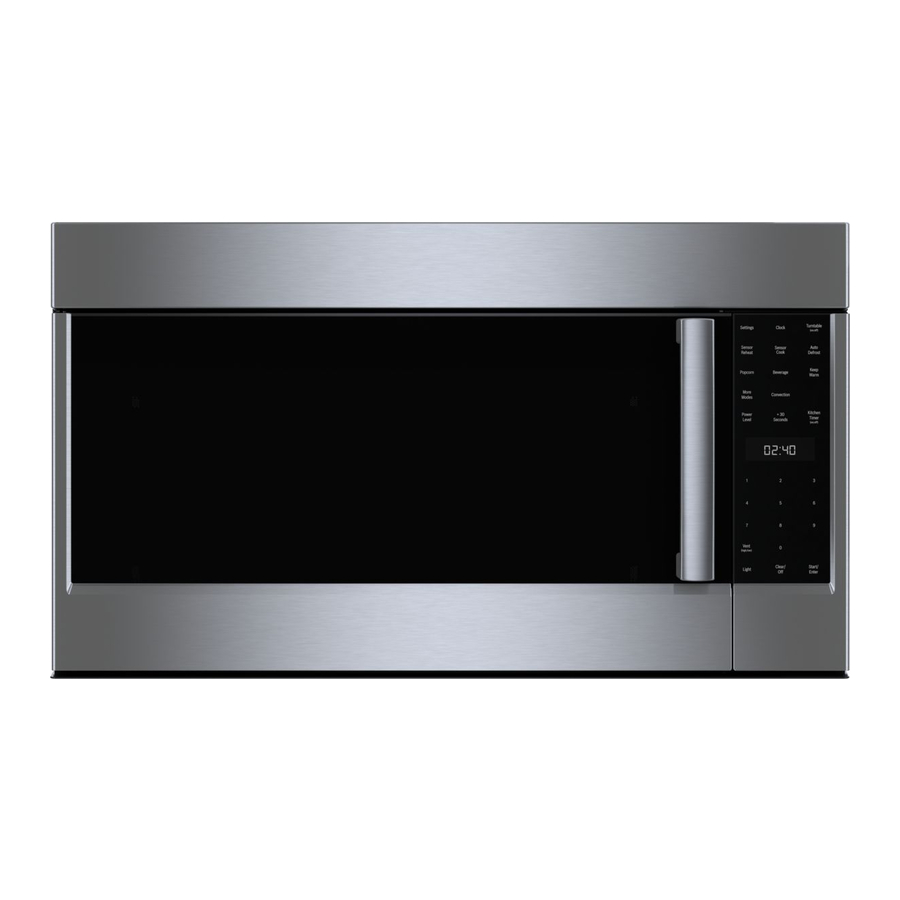
Bosch 800 Series Kurulum Talimatları Kılavuzu
Round pipes
An inner diameter of Ø 8" (203 mm) is recommended.

Installation Procedure

CAUTION
9
Ensure that there are no electric wires, gas or water
pipes in the area where holes are to be made.
If you are not sure, consult a qualified installer.

Preparing the installation

Mark a vertical center line on the wall from the ceiling
1.
to the lower edge of the extractor hood.
Align the drill template on the center line and the
2.
bottom edge of the extractor hood and glue on.
Mark positions for the screws and the contour of the
3.
attachment area.
Mark holes for the flue's angle brackets. The center of
4.
the angle bracket is marked with a hole. Place the
angle brackets in the center of the center line, align
them horizontally and mark the positions of the holes.

Fitting the wall retainer

Drill holes with Ø 5/16" (7.9 mm) for the angle
1.
bracket.
Press in the wall plugs flush with the wall.
2.
Screw screws (5x34 mm) into the wall plugs by hand
3.
in order to spread the plugs apart.
Unscrew screws.
4.
5.
Screw on the angle bracket for the flue duct.

Making the ceiling breakthrough

1.
Using a spirit level, extend the center line of the drill
template to the ceiling.
2.
Mark the ceiling breakthrough (Ø 8 1/2" (216 mm)) at
least 4 5/8" (117 mm) away from the wall.

Making the wall breakthrough

Using a spirit level, extend the center line of the drill
1.
template to the ceiling.
Depending on the curved section of the wall
2.
breakthrough (Ø 8 1/2" (216 mm)) mark at least 26 1/
2" (660 mm) above the bottom edge of the extractor
hood.
10

Checking the wall

The wall must be level, vertical and adequately load-
bearing.
The depth of the bore holes must be the same length
as the screws. The wall plugs must have a secure grip.
The enclosed screws and wall plugs are suitable for
solid brickwork. Suitable fasteners must be used for
other structures.
Mounting the extractor hood on the wall
WARNING
9
RISK OF INJURY
The appliance is heavy. To move the appliance, 2
people are required. Use only suitable tools and
equipment.
1.
Initially remove the protective foil from the back of the
appliance and, following installation, remove foil
completely.
2.
Mark the upper holes on the wall.
Note: Ensure that the holes are horizontal and aligned
centered on the center line.
3.
Drill the upper holes. Adhere to a distance of 1/4"
(6 mm) between the wall and screw head.
4.
Remove grease filters.
Hang the extractor hood on the upper screws on the
5.
wall.
Mark holes for the lower holes.
6.
Remove the extractor hood from the wall.
7.
8.
Drill the lower holes.
9.
Hang the extractor hood on the upper screws on the
wall.
10.
Tighten the upper and lower screws by hand.