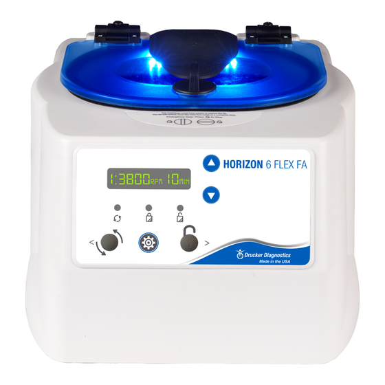
Drucker Diagnostics Horizon 6 FA Servis Kılavuzu - Sayfa 7
Teşhis Ekipmanları Drucker Diagnostics Horizon 6 FA için çevrimiçi göz atın veya pdf Servis Kılavuzu indirin. Drucker Diagnostics Horizon 6 FA 10 sayfaları.

7.8. Replacing the Control Board
•
The control board is accessible once the cabinet has been removed. Make certain
that all wire harnesses have been disconnected.
•
The control board has capacitors that will remain charged for a period after the
centrifuge is unplugged. Make certain to use standard precautions for handling
potentially charged capacitors when working with the control board.
•
The control board is held in place with six screws. Use a #2 Philips driver to remove
the screws. The board is now free to remove.
•
To install the control board, make certain that the six posts line up with the holes
in the control board and use a # 2 driver to install the screws.
7.9. Removing the motor
•
Remove the cabinet assembly as previously described.
•
Flip the base assembly up‐side down and remove the three screws that are
securing the exhaust cover and set aside.
•
Remove the six screws that hold the guard bowl
•
Lift the base assembly off the guard bowl and set it aside
•
Disconnect the motor wire connectors.
•
Remove the ground connection with a nut driver.
•
Flip the guard bowl.
•
The motor is held in place with four #8 Nylok nuts. Remove them with an 11/32"
nut driver.
•
Slide the motor out of the guard bowl's motor well.
DRUCKER DIAGNOSTICS
HORIZON 6 SERVICE MANUAL
SM024
REV A
7
