Daikin R32 Split Series Kurulum Kılavuzu - Sayfa 4

Fan Daikin R32 Split Series için çevrimiçi göz atın veya pdf Kurulum Kılavuzu indirin. Daikin R32 Split Series 14 sayfaları. R32 split series
Ayrıca Daikin R32 Split Series için: Kurulum Kılavuzu (17 sayfalar), Kurulum Kılavuzu (16 sayfalar), Kurulum Kılavuzu (16 sayfalar), Kurulum Kılavuzu (16 sayfalar), Kurulum Kılavuzu (17 sayfalar), Kurulum Kılavuzu (16 sayfalar), Kurulum Kılavuzu (20 sayfalar), Kurulum Kılavuzu (14 sayfalar), Kullanım Kılavuzu (16 sayfalar), Kullanım Kılavuzu (16 sayfalar), Kullanım Kılavuzu (8 sayfalar), Kurulum Kılavuzu (17 sayfalar), Kurulum Kılavuzu (16 sayfalar), Kurulum Kılavuzu (20 sayfalar), Kurulum Kılavuzu (20 sayfalar), Kurulum Kılavuzu (16 sayfalar), Kurulum Kılavuzu (16 sayfalar), Kurulum Kılavuzu (14 sayfalar), Kurulum Kılavuzu (14 sayfalar), Kurulum Kılavuzu (16 sayfalar), Kurulum Kılavuzu (17 sayfalar), Kurulum Kılavuzu (20 sayfalar), Kurulum Kılavuzu (13 sayfalar)
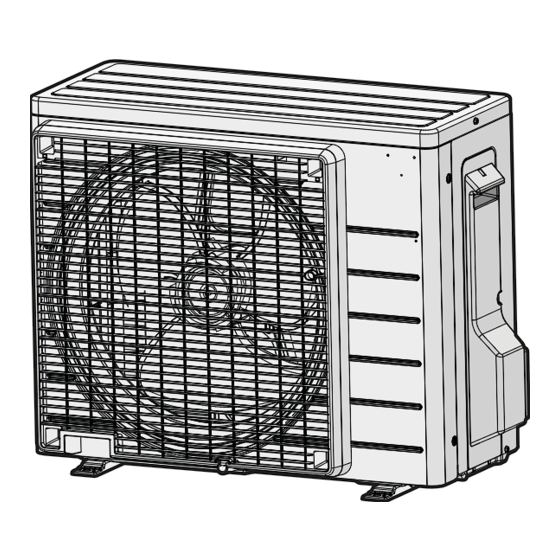
Daikin R32 Split Series Kurulum Kılavuzu

Accessories

A
Mounting plate
D
Wireless remote
controller
G
Dry battery AAA.
LR03 (alkaline)
K
Insulation tape
N
General safety
considerations
Q
Warranty

Choosing an Installation Site

• Before choosing the installation site, obtain user approval.
1.

Indoor unit

• The indoor unit should be positioned in a place where:
1) the restrictions on the installation requirements specified in "Indoor Unit Installation Diagram" on page 4 are met,
2) both the air inlet and air outlet are unobstructed,
3) the unit is not exposed to direct sunlight,
4) Install so that drainage occurs easily,
5) the unit is away from sources of heat or steam,
6) there is no source of machine oil vapor (this may shorten the indoor unit service life),
7) cool/warm air is circulated throughout the room,
8) the unit is away from electronic ignition type fluorescent lamps (inverter or rapid start type) as they may affect the remote
controller range,
9) no laundry equipment is nearby.
2.

Wireless remote controller

• Turn on all the fluorescent lamps in the room, if any, and find a location where the remote controller signals are properly
received by the indoor unit (within 23ft (7m)).
3
B
Mounting plate
fixing screw
M4 × 1"
1
(M4 × 25mm)
E
Remote controller
holder
1
H
Indoor unit fixing
screw
2
M4 × 1/2"
(M4 × 12mm)
L
Operation manual
1
P
SSID sticker with
release paper
(attached to the unit)
1
1
C
Titanium apatite deodorizing
filter
7
F
Remote controller
holder
fixing screw
1
M3 × 13/16"
(M3 × 20mm)
J
Screw cover
2
M
Installation
manual
1
*
2
Attach the sticker to the sticker
attachment area on the cover page
of the operation manual and keep
it safe.
*2 The installer should inform the user that it is not necessary to
attach the QR code portion of the SSID sticker.
*1 The 18/24 class models have 3 screw covers.
2
2
*1
2
1
1
English