Daikin R32 Split Series Kurulum Kılavuzu - Sayfa 6

Fan Daikin R32 Split Series için çevrimiçi göz atın veya pdf Kurulum Kılavuzu indirin. Daikin R32 Split Series 14 sayfaları. R32 split series
Ayrıca Daikin R32 Split Series için: Kurulum Kılavuzu (17 sayfalar), Kurulum Kılavuzu (16 sayfalar), Kurulum Kılavuzu (16 sayfalar), Kurulum Kılavuzu (16 sayfalar), Kurulum Kılavuzu (17 sayfalar), Kurulum Kılavuzu (16 sayfalar), Kurulum Kılavuzu (20 sayfalar), Kurulum Kılavuzu (14 sayfalar), Kullanım Kılavuzu (16 sayfalar), Kullanım Kılavuzu (16 sayfalar), Kullanım Kılavuzu (8 sayfalar), Kurulum Kılavuzu (17 sayfalar), Kurulum Kılavuzu (16 sayfalar), Kurulum Kılavuzu (20 sayfalar), Kurulum Kılavuzu (20 sayfalar), Kurulum Kılavuzu (16 sayfalar), Kurulum Kılavuzu (16 sayfalar), Kurulum Kılavuzu (14 sayfalar), Kurulum Kılavuzu (14 sayfalar), Kurulum Kılavuzu (16 sayfalar), Kurulum Kılavuzu (17 sayfalar), Kurulum Kılavuzu (20 sayfalar), Kurulum Kılavuzu (13 sayfalar)
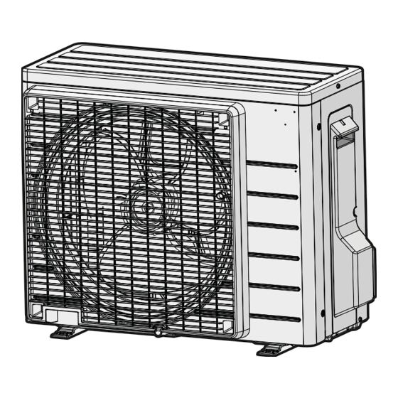
Daikin R32 Split Series Kurulum Kılavuzu

Indoor Unit Installation

1.

Installing the mounting plate

The mounting plate should be installed on a wall which can support the weight of the indoor unit.
1)Temporarily secure the mounting plate to the wall, make sure that the plate is completely level, and mark the drilling points
on the wall.
2)Secure the mounting plate to the wall with screws.
Recommended mounting plate retention spots and dimensions
09/12 class
Recommended mounting plate
retention spots (7 spots in all)
4-3/4 (120)
5-7/8 (150)
2-11/16 (68)
Place the pipe port
cover in this pocket.
18/24 class
Recommended mounting
plate retention spots
(7 spots in all)
4-3/4 (120)
5-7/8 (150)
2-11/16 (68)
* Depending on the model, the actual distance between the liquid pipe end and gas pipe end may differ from the distance between those symbols on the
mounting plate (the distance listed in this manual).
Always measure the actual distance between the liquid pipe end and gas pipe end before installing refrigerant pipes.
5
6-5/16 (160)
15-7/16 (392)
The removed pipe port cover can be kept in the mounting plate pocket.
Liquid pipe end
6-5/16 (160)
21-5/8 (550)
Place a leveler
on these tabs.
6-1/4 (158)
Liquid pipe end
Gas pipe end
2-9/16 (65*)
15-1/4 (387)
15-7/16 (392)
36-1/4 (920)
Removed pipe
port cover
Place a leveler
on these tabs.
Gas pipe end
2-9/16 (65*)
43-5/16 (1100)
11-1/2 (292)
4-5/8 (118)
9-1/16 (230)
6-5/16 (160)
2-11/16 (68)
A
Mounting
plate
6-5/16 (160)
15-1/4 (387)
21-5/8 (550)
2-11/16 (68)
Through-the-wall
hole φ2-9/16 (65)
Drain hose
position
Use a tape measure as
shown.
Position the end of the
tape measure at
.
4-5/8 (118)
Through-the-wall
hole φ3-1/8 (80)
9-1/16 (230)
Drain hose
position
unit: inch (mm)
English