anytronics Anyscene 1 Kurulum ve Kullanım Kılavuzu - Sayfa 4
Kontrolör anytronics Anyscene 1 için çevrimiçi göz atın veya pdf Kurulum ve Kullanım Kılavuzu indirin. anytronics Anyscene 1 6 sayfaları. Memory unit

4. Data Connections
The DMX data connections are provided via one 8-pin RJ45 with the pinouts detailed
below. If XLR style outputs are required the installer should use the AS180 as this will
supply power along with the other connectors.
Upon request Anytronics can also supply the D2228 connector PCB to provide extra
connectors for programming only.
5. DMX Requirements
5.1. DMX Loading
The maximum number of DMX receivers allowed along a single line is 32 devices without
the need for a buffer. If a DMX buffer is required within the system and an external DMX
source is also being used the Anyscene must all be linked with the external source and
then joined to the buffer for correct operation to the wider DMX line.
5.2. DMX Wiring
The DMX specification is based on the use of a single DMX source at one end of a twisted
pair with receiving equipment connected along the twisted pair, the final receiver must then
have a line termination resistor.
5.1. DMX Backup
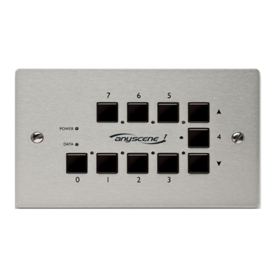
With the power applied, the Anyscene 1 will power up and, if no input DMX data is detected
within 2 seconds, it will start to output DMX data from the last used scene. If another
source of DMX data is detected in the system, the Anyscene will instead remain dormant
in standby/receive mode capturing the current DMX data with start code zero from
channels 1 - 32.
Whilst in this mode, the yellow Data LED will remain illuminated if valid data is being
received at any of the decoded addresses. If the memory write protection switch is in the
ON position, this captured DMX data can be stored as scenes as per the programming
section of this document.
If the DMX source is then disconnected or fails, the yellow Data LED on the Anyscene will
be extinguished. After two seconds the Anyscene will start to retransmit the last received
DMX data, providing a standby or DMX backup feature. None of the mimic LEDs will be
illuminated in this mode as the output data corresponds to the last data received rather
than to the contents of any of the scene memories.
Units 5 & 6 Hillside Industrial Estate
London Road, Horndean,
Hampshire, PO8 0BL
Tel +44 (0)23 9259 9410
Fax +44(0)23 9259 8723
Page 4 of 6
AT1042 Issue 1
Anyscene 1 Operating
Instructions
