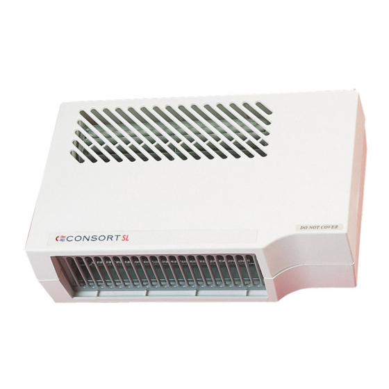
Consort BHM2SL Kurulum ve Kontrol Kılavuzu - Sayfa 3
Isıtıcı Consort BHM2SL için çevrimiçi göz atın veya pdf Kurulum ve Kontrol Kılavuzu indirin. Consort BHM2SL 4 sayfaları.

Important
When installed in a bathroom the unit must not be
connected via a plug and socket.
The heater must also be located in the appropriate
zone of the bathroom, in accordance with section
701 of the Wiring Regulations BS 7671). The appliance
should be fitted horizontally such that the cable entry
is uppermost. The unit must be mounted a minimum
of 1.8 metres from the floor, also a minimum of 150mm
below ceiling level or any other projecting surface. It
must also not be less than 350mm from any adjacent
projecting surface. The unit must not be located
immediately below a fixed socket outlet.
The heater is to be installed so that the appliance
cannot be touched by a person in the bath or
shower. The heater must not be installed in front of a
socket-outlet.
Means for disconnection must be incorporated in the
fixed wiring in accordance with the wiring rules. If the
supply cord is damaged, it must be replaced by the
manufacturer, its service agent or similarly qualified
persons in order to avoid a hazard.
Ensure that when in use the airstream is not
obstructed.
Warning – Do NOT place aerosols or similar containers
or materials susceptible to heat in the direct airstream.
Mounting Procedure
Using the mounting template supplied, position it
horizontally a minimum of 1.8 m from floor to
underside and mark the position of the three fixing
holes.
Drill and plug the wall suitable for No 8 screws.
Insert the two keyhole screws in wall leaving
approximately 2 mm gap between head and wall.
Position the appliance on the partially inserted wall
screws and secure the third wall screw immediately
above appliance.
Operation
When the appliance is connected to the mains supply,
the LED indicator will light up green, showing that the
power is available to the unit.
When the heat output has been enabled by a
controller, the LED indicator light will turn red.
This heater can only be used when connected to any
SL wireless controller.
Each SL controller can control any number of heaters
providing they are in the RF range.
SLPB
SLVT
SL wireless controllers
Please refer to the SL installation and control guide for
full operational details.
3
SLTI
SLVTB
64000284 Iss 01
