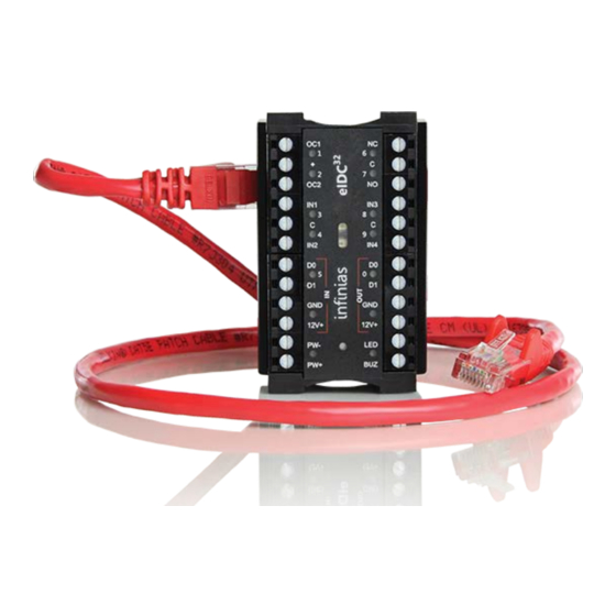
3xLogic infinias eIDC32 Hızlı Başlangıç Kılavuzu - Sayfa 12
Ağ Geçidi 3xLogic infinias eIDC32 için çevrimiçi göz atın veya pdf Hızlı Başlangıç Kılavuzu indirin. 3xLogic infinias eIDC32 17 sayfaları.

- 1. Important Safety Instructions
- 2. Before You Begin
- 3. Installation
- 4. Connect to an Ethernet Switch
- 5. Poe SWITCH
- 6. NON-Poe with MIDSPAN Poe INJECTOR
- 7. NON-Poe SWITCH
- 8. NON-Poe with POWER INJECTOR
- 9. DETERMINE the Eidc IP ADDRESS
- 10. CONFIGURE the Eidc with the WEB SERVER
- 11. CONNECT to the Eidc
- 12. CHANGE the Eidc to DHCP or STATIC IP MODE
- 13. WIRE the Eidc DOOR COMPONENTS
- 14. Eidc Web Server: Single Door Application
To wire the eIDC door components (refer to
1. Connect the magnetic lock or door strike.
• A magnetic lock or door strike can be powered by the eIDC
(12 VDC at 450 mA or less). This is a shared load.
• The two open collector outputs, OC1 and OC2 (Output 1 and
Output 2), provide a maximum of 12 VDC at 450 mA combined.
• OC1 and OC2 each have their own negative terminal (–)
terminal but share a positive (+) terminal.
• OC1 and OC2 are software configurable energized (E) or
de-energized (DE).
• A magnetic lock can be powered by the open collector output if
it draws less than 450 mA. If it draws more than 450 mA, then
it must be wired to the form C relay (5 A at 30 VDC) labeled NO
(normally open) and NC (normally closed) and powered
externally.
• Relay (Output 3) has separate terminals for common (C),
normally open (NO), and normally closed (NC), but the software
designation must match for proper status reporting.
2. Wire the status, shunt, and exit inputs.
• Input devices can be wired to eIDC Inputs (IN) 1 to 4.
• NO or NC is software configurable with Inputs 1 to 4.
• End of line resistance (EOLR) supervision is software
selectable and is supported with 1-kohm resistors.
3. Wire the readers.
• Reader IN (CRI) and Reader OUT (CRO) are internally
configured each having their own Data 0 (CR–), Data 1 (CR+),
DC+, and DC–.
• DC1– has a maximum load of 250 mA; DC2- has a maximum
load of 250 mA.
• The sum of all four open collectors (OC1 + OC2 + DC1 + DC2)
must not exceed 750 mA.
• There is a single terminal for optional Reader LED control and
optional Reader Buzzer control.
• Only readers can be wired to Data 0 (CR–), and Data 1 (CR+)
terminals.
12
Figure
2):
QSG-002 / 01-03-2017
