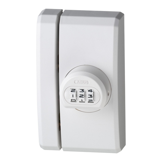
Abus FTS106 Kurulum ve Çalıştırma Talimatları - Sayfa 2
Kilitler Abus FTS106 için çevrimiçi göz atın veya pdf Kurulum ve Çalıştırma Talimatları indirin. Abus FTS106 2 sayfaları. Universal window lock

Abb./ g. / schéma /afb./ ill. 4
Schließkasten
Locking case
Gâche
Falzhöhe
Sluitkast
Rebate height
Scatola della
Recouvrement
serratura
Opdekmaat
Altezza
d'incassatura
0 – 29 mm
Rahmen
Frame
Cadre
Kozijn
Telaio
Abb./ g. /
Abb./ g./
schéma/
schéma/
afb. /ill. 5a
afb. / ill. 5b
F
Abb. / g./
Abb./ g./
schéma/
schéma/
afb. / ill. 6
afb. /ill. 7
2 mm
Abb. / g./
Abb./ g./
schéma/
schéma/
afb. /ill. 10
afb. / ill. 11
D
C1
D
C 2
Unterlagen für Höhenausgleich
Spacers
Entretoises
Opvulplaatjes
Spessori da livellamento
3 mm
Schlosskasten
Lock case
Boîtier
Slotkast
Cassa della serratura
Tür bzw. Fenster
Door/Window
Fenêtre
Deur/Raam
Porta risp. Finestra
2 mm
Abb./ g. /
schéma /
afb./ ill. 5c
Abb. / g. /
schéma /
afb./ ill. 8
A
C
B
B
C
A
Abb. / g. /
schéma /
afb./ ill. 12
3 mm
G
V. Installation instructions:
• Before installation, please check the setting of the window
or French door.
• If necessary, readjust the ttings so that the window (French door)
opens and closes perfectly.
• Also check whether your window/French door complies with the
minimum dimensions shown in g. 1.
• The depths of the drilled holes and screw lengths must be adjusted
to the local conditions.
• Avoid the drill or screws from coming out at the back!
Possibly work with drill stopper or shorten the existing screws.
• When drilling, do not damage any moving parts, seals or glass panes.
Installation:
Fitting the lock case:
1. Screw on the knob supplied loose through hole "F" using the Phillips
screwdriver ( g. 5a). The screw is already in the lock case (1).
For DIN left ( g. 5c), for DIN right ( g. 5b).
2. Adjusting the personal code:
The number combination of knob is set to 0-0-0 in the factory.
Adjust the personal code as follows:
a) In the setting 0-0-0, hold the side pin in.
b) Adjust your personal code.
c) Release the side pin again, the new code is now adjuste.
We recommend that you note the code and keep the note
in a safe place. ABUS cannot tell what the secret code is.
3. Remove the cover cap (4) from the lock case (1) from below by pressing
on the catch points ( g. 6). Undo the locking bolt.
4. Hold the lock case (1) in the required position against the window
casement or door, at a distance of 2 mm to the edge ( g. 7).
5. Mark and pre-drill hole position A and B (for PVC windows and doors
also C) ( g. 8 and drilling table).
6. Screw on lock case (1). For holes A (depending on rebate height),
use screws 4.2 x 16 mm or 4.2 x 9.5 mm (use screwdriver with magnetic tip).
Holes B (C) screws 5.5 x 60 mm.
Fitting the locking case:
The lock case (1) and striking plate (2) must be on the same level ( g. 4).
To compensate for the di ering rebate heights, the striking plate (2)
is lined, using the screw-on strip (3) and/or the spacers (7).
Rebate height:
from 14 mm [with screw-on strip (3) and possibly shims (7)].
1. Hold the screw-on strip (14 mm high) on the same level and at a parallel
distance of 3 mm to the lock case (1) ( g. 9). Ensure that the screw-on
strip (3) is in the right position.
2. Mark and pre-drill bore holes C1 and C2 ( g. 10 and drilling table).
3. Line screw-on strip (3) with spacers (7) if necessary (rebate height larger
than 14 mm). Screw tight with screws 5.5 x 60 mm.
4. Drill in the middle through the slanting screw holes D at the same
Abb./ g./
angle to the wall (see drilling table). If this is not possible, drill vertically.
schéma/
Then place the two wedge-shaped washers (6) in holes D.
afb./ ill. 9
5. Screw 2 more screws 5.5 x 60 mm into holes D.
6. Remove the cover cap (5) from the striking plate (2) from below by
3 mm
pressing on the catch points ( g. 11).
7. Screw striking plate (2) to screw-on strip with 3 screws M6 x 25 mm.
Check function:
Locking bolt must run freely into the striking plate (2) when closing.
8. Press on both cover caps.
Rebate height: 0 to 13 mm (possibly with shims).
1. Remove the cover cap (5) from the striking plate (2) from below
by pressing on the catch points ( g. 11).
2. Hold striking plate (2) centrally on the same level and at a parallel
distance of 3 mm to the lock case (1) ( g. 12).
3. Mark and pre-drill holes position E1 to E3 (Fig. 13) (see drilling table).
4. Line striking plate (2) with spacers (7) if necessary and screw tight with
3 screws 5.5 x 60 mm.
Check function:
Locking bolt must run freely into the striking plate (2) when closing.
Abb./ g./
schéma /
afb./ ill. 13
5. Press on both cover caps.
VI. Operation
E2
FTS 106 can be locked without a key by turning the knob
(possibly adjust code). To open, enter the number combination –
your personally adjusted code number – and turn the knob back.
The number wheels should be changed again after locking and also
after opening unintentionally.
E1
E3
