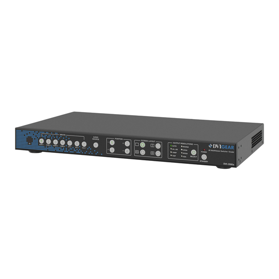
DVIGear DVI-3580a Hızlı Başlangıç Kılavuzu - Sayfa 3
Anahtar DVIGear DVI-3580a için çevrimiçi göz atın veya pdf Hızlı Başlangıç Kılavuzu indirin. DVIGear DVI-3580a 9 sayfaları. 4k multiviewer switcher, scaler
Ayrıca DVIGear DVI-3580a için: Hızlı Başlangıç Kılavuzu (8 sayfalar)

4K MultiViewer Switcher / Scaler
Installation
1.)
Rack Mount Ears and Removable Feet:
Add or remove these accessories as needed.
2.)
Video Sources and Destinations:
Connect each video source device to
the HDMI, DisplayPort or VGA inputs
on the rear of the DVI-3580a as
needed. Next, connect the displays or
downstream devices to the HDMI output
and/or the HDBaseT output. The HDBaseT
output only supports extension of audio, video, and POH. The RS-232, LAN, and IR signals cannot
be extended over the link. DVIGear
grade cable for the HDBaseT link.
3.)
Audio Sources and Destinations:
jacks accompanying the appropriate video signals as needed. Next, connect any downstream
audio devices to the appropriate audio outputs as needed.
4.)
Control Connections:
(built-in Web GUI or Telnet), RS-232, IR Remote Control, and Front Panel selections. The most
intuitive, versatile control method is the built-in Web GUI (see page 7).
To control the unit via the
standard (straight-through) LAN cable. Set the IP address of the control PC to be within the
same subnet as the unit. Next, open a web browser and input the IP address of the unit. By
default, the unit has an IP address of
To view the current IP address at any time, press and hold the Audio Source Button on the front
panel or IR remote for 5 seconds and the current IP will be displayed on the screen.
To control the unit via the
Default values:
5.)
Power:
First, supply power to the
Next, supply power to the DVI-3580a. To do this, plug the AC Power Cord into the receptacle
on the unit and then into an outlet. Switch the unit ON using the master switch on the rear of
the unit. This switch, along with the red power LED on the front panel, will remain illuminated
when power is supplied to the unit and the master switch is turned ON. The unit may need to be
toggled out of standby mode. When the unit is in standby, the standby button on the front panel will
light up green. Pressing this button will bring the unit out of standby.
After the unit is powered ON and is out of standby mode, supply power to the
Note 2 – WARNING: The HDBaseT port is designed to connect to compatible DVIGear products only (e.g. DVI-7520-RX).
Do not connect any device to the HDBaseT port of this product unless you are sure it is compatible. Do not connect any
HDBaseT device to the LAN port of the DVI-3580a. Connecting incompatible devices may cause harm to the devices.
Please use the preferred cable termination scheme (T568B) for all HDBaseT connections throughout the installation (see
the User Manual for more information). It is typical for HDBaseT receivers to operate at high temperatures. Care must
be taken to ensure airflow through the Rx unit is not restricted in any way.
recommends using CAT6A S/FTP (500 MHz) 23AWG high-
®
See the warning below.
Connect any external audio sources to the 3.5mm mini-
The unit may be controlled via a variety of options, including LAN
LAN
port, connect it to the network or directly to a PC using a
RS-232
port, connect to the unit using a straight-through cable.
baud rate: 9600; data bits: 8; stop bits: 1; parity: none; flow control: none.
destination
Quick Start Guide
(2)
192.168.100.100
and DHCP Mode disabled.
devices.
DVI-3580a
source
devices.
3
