GAC ADD103B-24 Hızlı Başlangıç Kılavuzu - Sayfa 3
Kontrolör GAC ADD103B-24 için çevrimiçi göz atın veya pdf Hızlı Başlangıç Kılavuzu indirin. GAC ADD103B-24 5 sayfaları. Integral electric actuator
4
INSTALLATION
•
Use an overspeed shutdown device, independent of the governor system, to prevent loss of engine control which may
cause personal injury or equipment damage.
•
Do not rely exclusively on the governor system electric actuator to prevent overspeed. A secondary shutoff device, such
as a fuel solenoid must be used.
Before installing the actuator to the fuel pump, make sure that the engine can NOT be started. Remove the battery connection
from the starter-motor and depress the emergency STOP button.
You must keep the actuator energized with the battery
NOTE
voltage until the installation is completed.
1.
Remove the plug in the access port (Figure 1).
Once the plug is removed, make sure no con-
tamination or fragments can get into the fuel
pump.
2.
Apply clean diesel fuel to the o-ring (Figure 2) included with the
actuator. This allows the actuator to slide easily into position on the
pump and protects the o-ring.
3.
Temporarily connect the actuator's leads to the Battery terminals
on the speed control unit. This will energize the actuator and place
the actuator's lever at the full-fuel position. Placing the actua-
tor in the full fuel position ensures the lever properly engages the
pump's fuel-metering valve linkage.
4.
See Figure 3 (before energizing actuator) and Figure 4 (actuator is
energized) and notice the positional difference of the lever located
on the bottom of the actuator. Battery polarity does not have to be
observed with respect to the actuator coil.
5.
With the engine stopped, place the fuel-metering valve linkage in
the fuel pump in full fuel position (Figure 5).
Do not force the actuator into position. If you feel any ob-
struction, simply rotate the actuator further counter clock-
wise while inserting it into pump.
Figure 1
ACCESS PORT PLUG
Figure 2
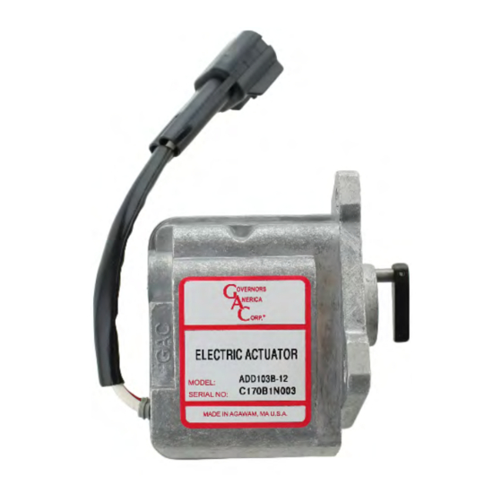
ACTUATOR LEADS
SCREW MOUNTING HOLES
Figure 3
BEFORE
ENERGIZING ACTUATOR
Figure 5
3
103 Series Integral Electric Actuator 4-2021-D2
Governors America Corp. © 2021 Copyright All Rights Reserved
TOP
O-RING
VALVE LINKAGE
Figure 4
ACTUATOR ENERGIZED
PIB2045