GAC ADD103B-24 Hızlı Başlangıç Kılavuzu - Sayfa 5
Kontrolör GAC ADD103B-24 için çevrimiçi göz atın veya pdf Hızlı Başlangıç Kılavuzu indirin. GAC ADD103B-24 5 sayfaları. Integral electric actuator
5
WIRING
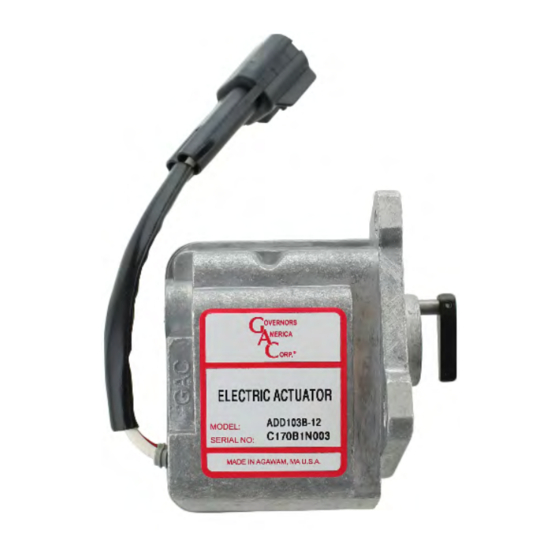
The 103 Series Electric Actuator is designed in both a 12 V DC or 24 V DC (B-Series) and the a 12 V DC L-Series. These actuator
models are identified in Chart A. You must be sure that the actuator voltage matches the battery supply voltage when ordering the
actuator. An actuator cable harness is used to connect the 103 Series actuator to the selected GAC speed control unit. There are no
polarity connections from the speed control unit to the actuator which need to be observed. For more information on additional wiring,
see installation manual for your specific to the speed control unit.
PREPARING THE FUEL PUMP
Before starting this procedure, make sure that the upper sur-
face of the pump is clean of all dirt and grime. Do not force or
over-tighten any connections while completing this procedure.
1.
Check the clearance on the Overshoot Protection Screw.
This screw may need to be replaced with a shorter screw.
A 10 mm M6 screw is recommended. This will provide
the adequate clearance needed to install the 103 Series
actuator.
2.
Adjust droop by loosening the locking-bolt and turn the
Droop Control allen screw CW until it cannot be turned
any further.
3.
Adjust the Allen Screw in a counter-clockwise direction
one and half turns and tighten lock nut.
4.
Set the no-load engine speed to 1950 RPM by loosen-
ing the Trunnion (Locknut) and adjusting the Speed Set
Screw. This adjustment requires turning the Speed Set
Screw approximately nine turns clockwise.
5.
Once you have the engine running at 1950 RPM, shut the
engine down and disconnect the starter-motor from the
battery.
6
TROUBLESHOOTING
If the electronic governor system fails to operate and the actuator is suspected, the following tests can determine the integrity of the
103 Series actuator.
MEASURE COIL RESISTANCE at ROOM TEMPERATURE
Check the resistance of the coil by disconnecting the actuator from the control unit and connecting your meter to the ends of the wires
coming from the actuator. This resistance should be approximately:
MEASURE COIL ISOLATION
Check the resistance from one wire to the housing of the actuator, then from the remaining wire to the housing. In both cases you
should get a reading >1M Ω
CHECKING FOR PHYSICAL OBSTRUCTION
1.
Remove the actuator from the pump.
2.
Hold the actuator with the lever side down.
3.
Manually move the actuator's shaft through its entire range of motion by depressing the actuator lever. You should not feel any
binding or sticking.
4.
Energize the actuator to full fuel (follow steps in speed control publication) while observing the movement of the lever.
5.
The actuator should operate smoothly throughout its entire stroke without any interruptions in motion.
6.
If the 103 Series actuator passes these tests, the problem is likely elsewhere in the speed control unit, speed sensor or fuel system.
Refer to the speed control unit troubleshooting publication or fuel pump information.
B - SERIES
2.3 Ω
12 V DC
5.3 Ω
7.8 Ω
24 V DC
5
103 Series Integral Electric Actuator 4-2021-D2
Governors America Corp. © 2021 Copyright All Rights Reserved
L-SERIES
12 V DC
PIB2045