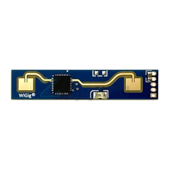
Hi-Link HLK-LD2410 Kullanıcı Kılavuzu - Sayfa 13
Kontrol Ünitesi Hi-Link HLK-LD2410 için çevrimiçi göz atın veya pdf Kullanıcı Kılavuzu indirin. Hi-Link HLK-LD2410 15 sayfaları. Human presence sensing module

Shenzhen Hi-Link ELectronics Co.,Ltd
7.Radome Design Guideline
7.1 Effects of Radomes on mmWave Sensor Performance
• Radar waves are reflected on the radome boundary
• Losses in total radar radiated or received power
• The reflected wave enters the receiving channel, affecting the isolation between the
transmitting and receiving channels
• Reflections may degrade the standing wave of the antenna, further affecting the antenna gain
• Radar waves will suffer loss when propagated in the medium. In theory, the higher the
frequency, the greater the loss will be
• Electromagnetic waves undergo a certain degree of refraction as they pass through a medium
• Affects the antenna's radiation pattern, which in turn affects the sensor's coverage
7.2 Radome Design Principles
•Structural shape of the radome
•The surface is smooth and flat, and the thickness is uniform. Such as plane or spherical
surface, can not be uneven.
•If there is a surface coating, it must not contain metals or conductive materials.
•Directly above the antenna, the radome is parallel to the antenna plane.
•Height H from the antenna to the inner surface of the radome
•The ideal height is an integer multiple of the half wavelength of the electromagnetic wave in
the air.
•
,where m is a positive integer, co is the speed of light in vacuum, and f is the
working center frequency.
•For example, the center frequency of 24.125GHz, its half wavelength in air is about 6.2mm.
• Radome thickness D
•The ideal thickness is an integer multiple of the half wavelength of the electromagnetic wave
in the medium.
material.
•For example, a certain ABS material
HLK-LD2410
,where m is a positive integer and
is the relative permittivity of the radome
=2.5, its half wavelength is about 3.92mm.
11
User Manual
