Cell2 SDF104H Kurulum ve Kullanım Kılavuzu - Sayfa 6
Amplifikatör Cell2 SDF104H için çevrimiçi göz atın veya pdf Kurulum ve Kullanım Kılavuzu indirin. Cell2 SDF104H 12 sayfaları. Siren amplifier
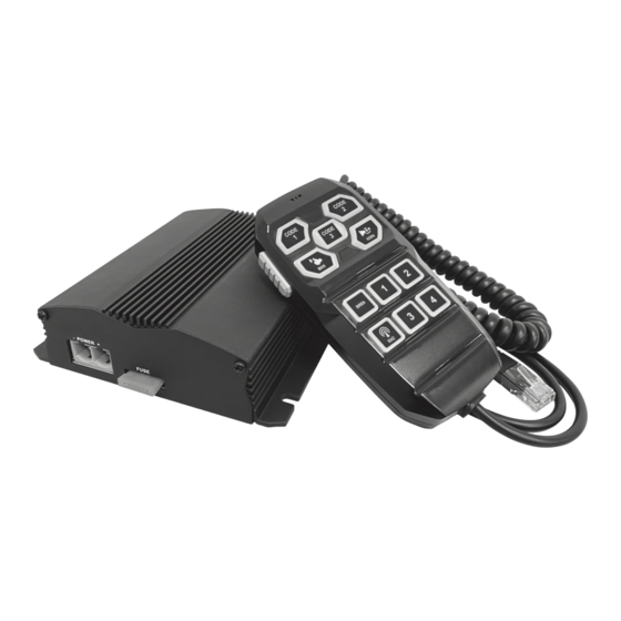
Power Wire Terminal Block (Connector A)
● Power +VDC & -GND
1. Connect to the positive (+) battery terminal. Fuse each wire independently @35 Amps (user-supplied).
DO NOT install these fuses until the wiring for the entire system has been completed.
2. Connect to the vehicle's chassis ground (typically adjacent to the battery).
3. Plug the Connector A into the siren amplifier.
Control Wire Harness (Connector B)
● Ignition Activation (IGN) input
Apply +VDC continuously to RED wire to enable the siren system. Connect this wire to a positive
circuit controlled by the vehicle ignition switch to allow the siren amplifier to be turned on & off together.
The system does not operate without this Ignition Activation. DO NOT directly connect this wire to the
battery as this may drain battery.
● SW1 Output
Connect to auxiliary device power up to 5 Amps max. or use as Lightbar function activation switch.
● SW2 Output
Connect to auxiliary device power up to 5 Amps max. or use as Lightbar function activation switch.
● SW3 Output
Connect to auxiliary device power up to 5 Amps max. or use as Lightbar function activation switch.
● SW4 Output
Connect to auxiliary device power up to 5 Amps max. or use as Lightbar function activation switch.
● Speaker Out
Connect the BLUE (SPK+) and BROWN (SPK-) wires to one 100W 11-ohm impedance speaker.
● Radio Re-broadcast
Connect WHITE and GREY wire to the speaker output of a radio console.
● Horn Ring Transfer (HRT) input
Apply +VDC continuously to PINK wire for Air Horn tone.
- 4 -