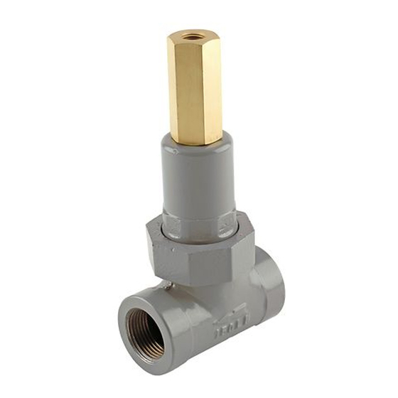
Emerson 1805-7 Series Kullanım Kılavuzu - Sayfa 3
Kontrol Ünitesi Emerson 1805-7 Series için çevrimiçi göz atın veya pdf Kullanım Kılavuzu indirin. Emerson 1805-7 Series 8 sayfaları. Relief valves

A6671
INLET PRESSURE
OUTLET PRESSURE
ATMOSPHERIC PRESSURE
Principle of Operation
See Figure 2. Relief valves respond to changes in
upstream pressure. If upstream pressure increases
and exceeds the relief valve setting, the valve will
open and allow gas to vent to the atmosphere. When
upstream pressure returns to normal level (below the
setting of the relief valve), the relief valve automatically
closes and normal system operation resumes.
In the 1805 Series relief valves, the upstream pressure
registers underneath the diaphragm. Gas reaches
the diaphragm through the space between the O-ring
holder and the valve guide orifice in 3/4 and 1 NPT
bodies or through registration holes in the valve guide
UPPER
SPRING
SEAT
DIAPHRAGM
HEAD
UNION NUT
O-RING
HOLDER
O-RING WASHER
Figure 2. 1805 Series Operational Schematic
DIAPHRAGM
VALVE GUIDE
ORIFICE
O-RING
BODY
O-RING
orifice in 1-1/2 and 2 NPT bodies. When the upstream
pressure increases beyond the spring setting, the force
on the diaphragm overcomes spring compression.
The O-ring holder moves upward, carrying the O-ring
away from the valve seat. This opens the flow line,
allows gas to flow to the atmosphere and relieves the
overpressure condition. When upstream pressure
registered on the diaphragm decreases to a level
below that of the spring setting of the relief valve, the
spring force pushes the diaphragm plate and O-ring
holder toward the valve seat. Contact between O-ring
and valve seat prevents further flow to atmosphere.
1805 Series
3
