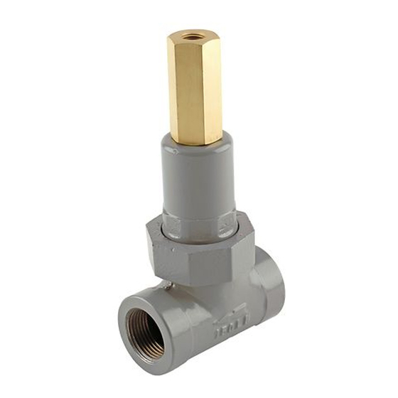
Emerson 1805-7 Series Kullanım Kılavuzu - Sayfa 4
Kontrol Ünitesi Emerson 1805-7 Series için çevrimiçi göz atın veya pdf Kullanım Kılavuzu indirin. Emerson 1805-7 Series 8 sayfaları. Relief valves

1805 Series
TYPE CS200IN
SET AT 8 IN. W.C. / 20 mbar
TYPE 1805 SET AT 40 psi /
2.8 bar ROTATE PIPING SO
DISCHARGE FROM RELIEF
VALVE MISSES REGULATOR
TYPE R622 ASSEMBLY
OR 4 SET AT 25 psi / 1.7 bar
INLET PRESSURE UP TO
750 psi / 51.7 bar
Installation
After unpacking, check the relief valve for shipping
damage. Remove pipe scale and other foreign
material from the connecting pipeline. Coat the male
pipe threads with a suitable pipe compound. The unit
can be installed in any position as long as the flow is in
the direction indicated by the arrow cast on the body.
Protect the outlet and vents from entrance of rain,
snow or other foreign material that may plug them.
Outdoor installations should include a rain cap
over the vents and outlet if they point upward.
Periodically check the openings to ensure that they are
not plugged.
Protect the relief valve against damage from vehicles
or other external sources.
4
AF9932
Figure 3. Typical Farm Tap Installation
TEST GAUGE CONNECTION
PLUGGED-OPTIONAL
HAND VALVE
OR PLUG COCK
OPTIONAL
Vents
!
Venting gas may accumulate and be
an explosion hazard under enclosed
conditions such as in pit or underground
installations. Install remote vent lines to
carry gas to a safe area.
If remote vent lines are necessary, use the
Type 1805-2, -3 or -7 which have 1/4 NPT vent
connections in the closing cap. Remove the screen
if one is present in the outlet, and install remote vent
lines in the outlet and closing cap openings. Remote
vent lines must have the largest practical diameter as
possible. The vent lines should be as short as possible
with a minimum number of bends or elbows.
WARNING
