Galaxy DX 29HP Kullanıcı El Kitabı - Sayfa 5
Alıcı-Verici Galaxy DX 29HP için çevrimiçi göz atın veya pdf Kullanıcı El Kitabı indirin. Galaxy DX 29HP 8 sayfaları. 10 meter amateur mobile transceiver
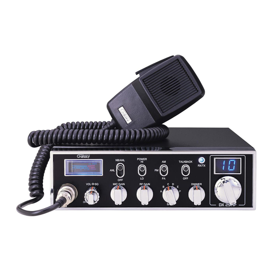
Operation
CONTROL FUNCTIONS
There are eleven controls and three indicators on the front panel of your
transceiver.
FRONT PANEL
1. MICROPHONE JACK. Used to connect microphone for voice source.
2. OFF/ON/VOLUME (inner dual concentric). Turn clockwise to apply power
to the unit and to set the desired listening level. During normal operation, the
VOLUME control is used to adjust the output level obtained either at the
transceiver speaker or the external speaker, if used.
3. SQUELCH (outer dual concentric). This control is used to cut off or
eliminate receiver background noise in the absence of an incoming signal. For
maximum receiver sensitivity it is desired that the control be adjusted only to
the point where the receiver background noise or ambient background noise is
eliminated. Turn fully counterclockwise then slowly clockwise until the
receiver noise disappears. Any signal to be received must now be slightly
stronger than the average received noise. Further clockwise rotation will
increase the threshold level which a signal must overcome in order to be heard.
Only strong signals will be heard at a maximum clockwise setting.
4. MIC GAIN. Adjust the microphone gain in transmit and PA modes. This
controls the gain to the extent that full talk power is available several inches
away from the microphone.
5. RF GAIN CONTROL. Use to reduce the gain of the receive signal under
strong signal conditions.
- 7 -
6. BAND SELECTOR. This switch is used to select the band.
7. DIMMER CONTROL. Controls the brightness of the meter lamp, channel
display digits and RX/TX LED.
8. CHANNEL SELECTOR. This switch selects any one of the forty channels
desired. The selected channel number is on the LED readout directly above the
Channel Selector knob.
9. METER. Indicates received signal strength and transmitter RF output power.
10. NB/ANL/OFF. In the ANL position, the Automatic Noise Limiter circuit is
activated. In the NB/ANL position, the RF Noise Blanker is also activated.
This Noise Blanker is very effective for repetitive impulse noise such as
ignition interference. Both ANL and NB are off when this switch is in "OFF".
11. RF POWER. This switch is used to select transmitting power. In the HI
position, the transceiver operates at 10 watts RF output power. In the LO
position, the transceiver operates at 1 watt RF output power.
12. MODE (PA/FM/AM) SWITCH. This switch is used to select PA, FM, AM
mode of operation. When you set to PA position, the transceiver acts as a
public address amplifier. Before operating PA, you must first connect an
external PA speaker (8 ohm, 4-watt) to the PA Speaker jack on the unit rear
panel.
13. TALKBACK/OFF. When this switch is in the TALKBACK position, it is
used to monitor your own voice in the radio speaker. For example, you could
use this feature to compare different Microphones.
14. RECEIVE/TRANSMIT INDICATOR. The receiver/transmit LED indicator
is located next to the channel indicator. When in receive, the LED will be blue.
When in transmit the LED will be red.
15. CHANNEL INDICATOR. Numbered LED indicates the selected channel
you wish to operate on.
-8-