AGS Merlin FAM 1 Kurulum ve Kullanım Kılavuzu - Sayfa 4
Kontrolör AGS Merlin FAM 1 için çevrimiçi göz atın veya pdf Kurulum ve Kullanım Kılavuzu indirin. AGS Merlin FAM 1 8 sayfaları. Gas service manual reset controller

FAM1
Installation
Introduction
It is recommended that the user reads this guide before using the system.
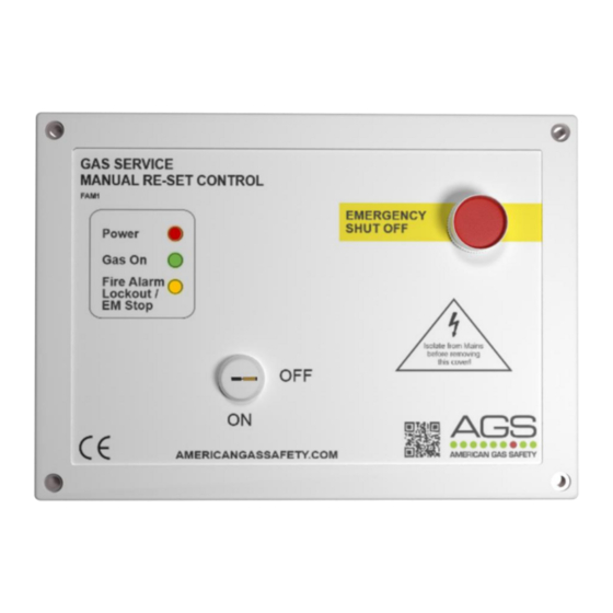
The FAM1 is an isolation panel with gas solenoid valve output. The FAM1 is designed to provide an effective
way of isolating gas supply by means of a key switch on the panel or by the operation of the emergency
shut off button. The FAM1 can be integrated with a BMS, fire alarm and remote shut-off device(s).
Mounting
Take care when making connections to line voltage connectors!
Any damage attempting to remove the circuit board may void any warranty!
All Class 2 wiring is to be installed within flexible tubing to maintain segregation between circuits!
Wiring of different circuits shall be separated by means of routing, clamping or barrier!
The control panel is designed for surface mounting using 4 mounting screws. Removing the cover on the
panel gives access to the circuit board. The PCB should be removed before drilling entry holes into the
case. A flush mount kit is available, comprising of a mounting bracket and decorative surround strip.
Connections Overview
UTILITY 1
Power Output for gas solenoid valve, 110-120VAC, Max 3A.
POWER
Line Voltage Input 110-120VAC Single Phase. 50-60Hz.
AUTO RESET & BMS
See sections: BMS Integration & Auto reset.
EM REMOTE
This terminal is for remote emergency shut-off buttons and
detailed on the circuit board as [EM REMOTE]. This is linked out as a factory setting. Remote emergency shut-off
buttons should be volt free and wired to the FAM1 using a plenum security cable, white, 18/2 (18AWG 2 conductor),
stranded, CMP or similar.
FIRE PANEL
The terminal for fire alarms is detailed on the circuit board as [FIRE PANEL]. This connection is linked out as a factory
setting. Fire alarms should be volt free and wired to the FAM1 using two-core cable.
BMS OUT
Terminal connections are available on the circuit board for Building Management systems etc.
Detailed on the circuit board as [BMS OUT - N/C, COM and N/O] (Normally Closed / Common / Normally Open). These
are dry contacts. This is a relay that changes state in alarm or when the utility is on/off.
Rev: 01
04-23
Installation & Operation Manual
4
