HIKOKI CB12-ST2 Teslim Talimatları - Sayfa 3
Testere HIKOKI CB12-ST2 için çevrimiçi göz atın veya pdf Teslim Talimatları indirin. HIKOKI CB12-ST2 16 sayfaları. Band saw stand

APPLICATIONS
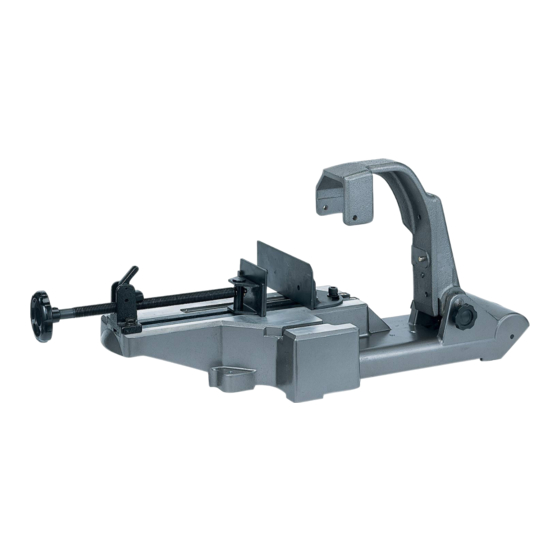
Band saw stand especially designed for stationary
implementation of right-angle cutting, angle cutting, and
contour cutting work, for use with the following HiKOKI
band saw: CB3612DA
For details regarding the latest available band saw, check
our general catalogue and other information.
SPECIFICATIONS
Model
Max. cutting
Round pipe
capacity*
90°
Square pipe
Round pipe
45°
Square pipe
Weight
* Maximum cutting capacity possible when a rotary band
saw is installed
HOW TO USE
1. Installing the band saw stand and switch holder
(1) Move the lever switch to the OFF position, and remove
the battery from the main tool unit.
(2) When the stopper bolt is loosened, the hinges of the
band saw stand will fall over backward (toward the
wheels) due to the force of the spring.
While loosening the stopper bolt, hold the top of the
hinges so that they do not fall over backward. (Fig. 2)
CB12-ST2
Φ115 mm
Width 100 mm x Height
100 mm
Φ50 mm
Width 50 mm x Height
50 mm
14.5 kg
Wheel
Stopper bolt
Fig. 2
(3) Align the hole in the side of pulley guard (A) with the D8
pin of hinge (A), and insert the D8 pin into the hole. (Fig. 3)
(4) One D6 knob bolt is provided on each of the front and
rear sides of hinge (B). Only tighten the one on the rear
side. (Fig. 3)
Pulley guard
(A)
Hole
Hinge (A)
D8 pin
NOTE
The switch holder needs to be installed in order to use
the band saw installed on the stand.
Switch holder
(standard
accessory
of CB3612DA)
(5) While pressing the switch lock, pull the switch and fi t the
switch holder into position.
This locks the switch in the ON position. (Fig. 4)
(6) Tighten the D6 knob bolt on the front side.
When the installation procedure has been correctly
carried out, the switch lock is held in the pressed
position. (Fig. 4)
Switch holder
Switch lock
Switch
3
English
D6
knob bolt
Rear side of
the band saw
Hinge (B)
Fig. 3
D6 knob bolt
Fig. 4
