Major tech MT935 Kullanım Kılavuzu - Sayfa 6
Ölçüm Cihazları Major tech MT935 için çevrimiçi göz atın veya pdf Kullanım Kılavuzu indirin. Major tech MT935 8 sayfaları. Phase rotation meter with rotary field direction
Ayrıca Major tech MT935 için: Kullanım Kılavuzu (8 sayfalar)

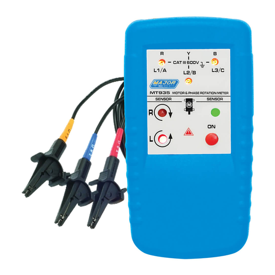
6.3. Determine the Motor Connection
1. Connect one end of the test leads to the Meter, make sure the L1, L2
and L3 test leads are connected to the corresponding jack.
2. Connect the alligator clamps to the other end of the test leads.
3. Connect the alligator clamps to the motor connections, L1 to U, L2 to V,
L3 to W.
4. Press the ON/OFF Button, the green ON indicator shows that the
instrument is ready for testing.
5. Turn the motor shaft half a revolution towards the right.
Note: The bottom of the Meter should be oriented towards the drive
shaft. See the Orientation Symbol on the Meter.
Note: Either the Clockwise or Counter Clockwise Rotary indicator
illuminates showing the type of rotary field direction present.
6.4. Magnetic Field Detection
• To detect a magnetic field, place the Motor and Phase Rotation
indicator to a solenoid valve.
• A magnetic field is present if either the Clockwise or the Counter
Clockwise Rotary indicator illuminate.
7. BATTERY REPLACEMENT
This Meter uses a 9V battery. To replace the battery, follow these steps.
1. Place the LCD side of the Meter down on a non-abrasive surface.
2. With a screwdriver, loosen the screw of the battery compartment and
remove the lid. Remove the old batteries.
3. Insert the new batteries while observing the battery polarity shown in
the battery compartment.
4. Secure the battery compartment lid back in position with the screw.
Note: The Meter contains alkaline batteries. Do not dispose of these
batteries with other solid waste. Used batteries should be disposed
of by a qualified recycle or hazardous materials handler.
8. SPECIFICATIONS
8.1. Determine Rotary Field Direction
Function
Nominal Voltage Rotary Direction
Nominal Voltage Phase Indirection
Frequency Range (fn)
Test Current (In per phase)
6
Range
1 to 400V AC
120 to 400V AC
2 to 400Hz
Less than 3.5mA
5
