GAPOSA M1A Referans Kılavuzu - Sayfa 8
Endüstriyel Ekipmanlar GAPOSA M1A için çevrimiçi göz atın veya pdf Referans Kılavuzu indirin. GAPOSA M1A 11 sayfaları. Safety brake
Ayrıca GAPOSA M1A için: Referans Kılavuzu (14 sayfalar)
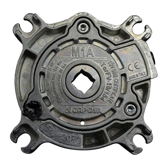
5. Insert the shaft support pin (with key or square in case of M1A and M2A) into the
safety brake hole smoothly; eventually check the alignment between the safety brake
hole, on one side, and the output shaft on the other side;
6. Avoid a snapping working of the shutter since it might cause the intervention of the
safety brake. A well-built side slide and good profiles assure a regular working of the
device;
7. Connect the safety brake electrical cable (complete with micro switch and NC contact)
to the STOP control in the motor control unit;
During installation, in order to avoid bad performances of the safety brake, do not
tamper the screws and the relative nuts on the central body; GAPOSA srl is not
responsible for damages caused by a wrong installation or an improper use.
TESTING INSTRUCTIONS
The testing process of the safety brake consists of:
1. An accurate check of a perfect installation, by making sure that all the fastening screws
of the base and of the safety brake are provided with suitable washers (preferably self-
locking washers) and perfectly tightened, Make also sure that the safety brake has not
been unduly opened.
2. A check of the safety brake regular working, while the shutter is rotating. Since it is
not possible to simulate a breakage in the transmission, you can make sure of the
good working of the safety brake by listening to the linking caused by the adjustment
of internal components. If this is clearly heard the safety brake has passed the working
test.
3. A check of the electrical continuity at the extremity of the micro-switch thread.
IMPORTANT: CHECK THAT THE SAFETY BRAKE HAS NOT UNDERGONE PREVIOUS
TESTS AND STRONG STRESSES.
8