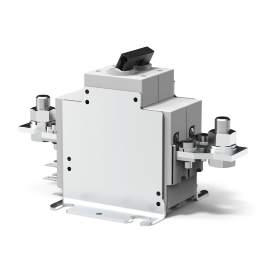
E-T-A 922 Series Kurulum Kılavuzu için Talimatlar - Sayfa 5
Anahtar E-T-A 922 Series için çevrimiçi göz atın veya pdf Kurulum Kılavuzu için Talimatlar indirin. E-T-A 922 Series 6 sayfaları. Battery isolation/main switches
Ayrıca E-T-A 922 Series için: Kurulum Kılavuzu (12 sayfalar)

Batterie-Schutzschalter/-Trenner / Battery Isolation/Main Switches
3
Die Fernauslösespule „FA" ist nur für Impuls-
betrieb geeignet. Es wird empfohlen, die
Spule über die „tote" Seite (II oder -2) (Fig.
7.a + 7.b) des Hauptstromkreises oder in
Reihe mit einem ggf. vorhandenen Hilfs-
kontakt „Schließer" (13/14, 23/24) zu schal-
ten (Fig. 7.c + 7.d).
11
12
b
a
13
14
24
23
≠ U
8. a 437: U
FA
Main
empfohlen/
recommended
SR
-
II
FE 3
b
a
11 13
4
5
I >
CB
FA
6
12
14
+
I
6 Auslösung
Die Typen 921 (einpolig) und 922 (zweipolig) wer-
den manuell oder durch einen Impuls auf die
Fernauslösespule ausgelöst.
Der Typ 437 wird durch Überlast oder durch einen
Impuls auf die Fernauslösespule ausgelöst.
8
3
The remote disconnect coil "FA" is impulse
rated only. It is recommended that this is con-
nected to the "dead" side of the main circuit
(II or -2) (fig. 7.a +7.b) or in series with one of
the pairs of make auxiliary contacts (13/14,
23/24), if these are available (fig. 7.c + 7.d).
falls vorhanden/if fitted:
SR: Schalter für FA- und FE-Steuerung/ switches for
remote ON and OFF control
CB: angebauter Schutzschalter zum Schutz der FE-Spule/
circuit breaker fitted for coil overload protection
11 - 12: Öffner/break/Si1
13 - 14: Schließer/make/Si2
a - b: FA-Spule /FA-coil
23 - 24: Schließer/make/Si2
FA: Fernausschaltspule/remote disconnection coil
FE: Ferneinschaltspule/ remote reconnection coil
8. b 437: U
= U
FA
Main
SR
-
II
23
FE 3
b
11 13
23
a
4
5
I >
CB
FA
6
24
12
14
24
+
I
6 Disconnection
Series 921 (single pole) and 922 (double pole)
can be disconnected manually or by an impulse
to the remote disconnection coil.
Series 437 trips either on overload or on an
impulse to the remote disconnection coil.
Batterie-Schutzschalter/-Trenner / Battery Isolation/Main Switches
5
Kunststoffgehäuse auf die Grundplatte (G)
aufsetzten und auf richtiges Einrasten des
Kipphebels achten. Das Gehäuse mit den
Schrauben (S2) befestigen.
Der Schutzschalter kann auf eine Profilschiene (PS)
im Schaltkasten aufgesteckt oder in einen kun-
denspezifischen Kasten mit 4 Schrauben ein-
gebaut werden (Fig. 4).
Alternativ dazu kann das Gerät auf einer Montage-
platte mit 4 Schrauben M8 befestigt werden (Fig. 5).
Fig. 8
SH = Kipphebel
G
= Grundplatte
K
= Kunststoffgehäuse
5
Locate the moulded enclosure on the base (G)
taking care to engage the switching handle with
the operating knob, tighten the screws (S2).
For non-automative applications, the switch unit
may be fitted to rail (PS) provided in a control
cabinet or mounted in a custom designed en-
closure by means of 4 bolts M4 (fig. 4), alternati-
veli the switch unit is provided with brackets for
base mounting by means of 4 bolts M8 (fig. 5).
SH
G
K
S1
S2
SH = switch handle
G
= housing base
K
= housing
PS
Fig. 4
Fig. 3
Fig. 5
5
