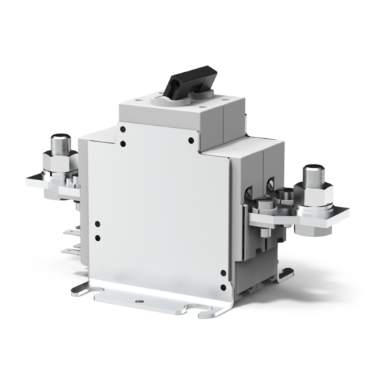
E-T-A 922 Series Kurulum Kılavuzu için Talimatlar - Sayfa 6
Anahtar E-T-A 922 Series için çevrimiçi göz atın veya pdf Kurulum Kılavuzu için Talimatlar indirin. E-T-A 922 Series 6 sayfaları. Battery isolation/main switches
Ayrıca E-T-A 922 Series için: Kurulum Kılavuzu (12 sayfalar)

Batterie-Schutzschalter/-Trenner / Battery Isolation/Main Switches
4 Ausbau
1
Versorgungsspannung abschalten.
2
Elektrischen Anschluss und Steuerleitungen
lösen.
3
Der Ausbau erfolgt in umgekehrter Reihenfolge.
5 Elektrischer Anschluss
Achtung!
Einpolig:
Bei Betriebsspannungen > 48 V auf die Pola-
rität achten (gekennzeichnet durch Aufkleber
auf der Haupt-Anschlussseite).
Zweipolig:
Der rote Kipphebel entspricht dem (+) Pol.
1
Stromversorgung abschalten.
2
Stromversorgungskabel von der Batterie auf
„I" anschließen (Fig. 6).
3
Steuerleitung und Hilfskontakte gemäß Fig. 7
(921/922) oder Fig. 8 (437) anschließen.
II
+ DC 180 V
I
M10x25
6
4 Removal
1
Disconnect power supply.
2
Disconnect the terminals and the control
cable.
3
Reverse the installation procedure.
5 Electrical connection
Caution:
Single pole:
Observe the correct polarity (identified by
label on the main connection side) when
operating voltages above 48 V are applied!
Double pole:
The red toggle identifies the positive pole (+).
1
Disconnect power supply.
2
Connect the main battery cable to terminal I
of the switch unit.
3
Connect the remote control circuitry and
auxiliary contacts as shown in fig.7 (921/922)
or fig. 8 (437).
schwarz/black
rot/red
Fig. 6
Batterie-Schutzschalter/-Trenner / Battery Isolation/Main Switches
Hinweise:
1
Die optionalen Hilfskontakte 13/14 und 23/24
sind Schließer, d.h. sie sind geschlossen,
wenn der Schalter sich in ON (EIN)-Stellung
befindet. Sie sind geeignet für Ausschalten
untergeordneter Stromkreise und der Wech-
selstromspule.
2
Die optionalen Hilfskontakte 11/12 sind Öff-
ner, d.h. sie sind geöffnet, wenn der Schal-
ter sich in ON(EIN)-Stellung befindet. Sie
sind geeignet um Notstromkreise und ande-
re Einrichtungen zu schalten, die beschaltet
sein müssen, wenn er Hauptschalter OFF
(AUS) ist.
11
12
a
b
13
14
23
24
7. a 921: U
= U
FA
Main
SR
-
II
b
a
11 13
FE 3
4
5
CB
FA
6
12
14
+
I
≠ U
7. c
921: U
FA
Main
empfohlen/
recommended
SR
-
II
FE 3
b
a
11 13
4
5
CB
FA
6
12
14
+
I
Note:
1
Optional auxiliary contacts 13/14 and 23/24
are make contacts, i.e they are closed when
the switch is in the ON position. These are
suitable for disconnecting ancillary systems
and for alternator field winding disconnection.
2
Optional auxiliary contacts 11/12 are break
contacts, i.e they are open when the switch
is in the ON position. These are suitable for
connecting emergency circuits and other
equipment which must remain energised
when the main switch is OFF.
falls vorhanden/if fitted:
SR: Schalter für FA- und FE-Steuerung/ switches for
remote ON and OFF control
CB: angebauter Schutzschalter zum Schutz der FE-Spule/
circuit breaker fitted for coil overload protection
11 - 12: Öffner/break/Si1
13 - 14: Schließer/make/Si2
a - b: FA-Spule /FA-coil
23 - 24: Schließer/make/Si2
FA: Fernausschaltspule/remote disconnection coil
FE: Ferneinschaltspule/ remote reconnection coil
7. b 922: U
= U
FA
Main
SR
+2 -2
23
b
11 13
23
3
a
FE
4
5
CB
FA
6
24
+1 -1
12
14
24
≠ U
7. d 922: U
FA
Main
empfohlen/
recommended
SR
+2 -2
23
3
b
a
11 13
23
FE
4
5
CB
FA
6
12
24
+1 -1
14
24
Fig. 7
7
