A-M Systems 2100 Kullanım Kılavuzu - Sayfa 5
Ölçüm Cihazları A-M Systems 2100 için çevrimiçi göz atın veya pdf Kullanım Kılavuzu indirin. A-M Systems 2100 19 sayfaları. Isolated pulse stimulator

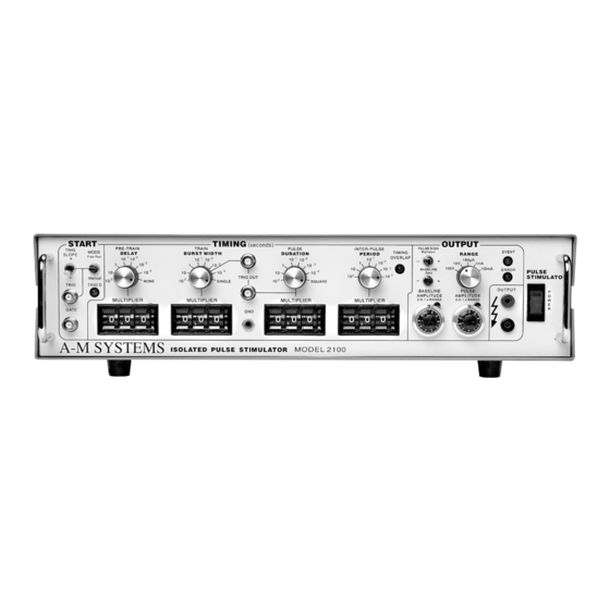
Controls and Connectors
The controls for the Model 2100 are grouped in three sections:
when a pulse or burst of pulses begins;
or more pulses; and
Start
Determines the polarity of valid trigger pulses
TRIG SLOPE:
(positive or negative edges in the trigger signal).
Controls waveform initiation. When set to
MODE:
one timing cycle immediately follows the last. When
momentarily placed in the
starts immediately. When the switch is in the center
position, timing cycles start when valid triggering events
occur.
This LED lights up when a timing cycle is in process
TRIG'D:
and continues until the burst is completed.
This BNC connector allows a signal from an external
TRIG:
source to initiate timing cycles. It is set for standard TTL
levels.
This BNC connector allows a signal from an external source to restrict the final
GATE:
output signal. This input must be at a logical high (or open-circuited) in order for the
Model 2100 to recognize either manual or automatic trigger events.
Valid triggers (represented by the arrows in the figure) can occur only when the gate
is at logical high. Note that the up arrow would apply only if
the down arrows would apply only if
Note: Triggers have no effect if the system has not completed its response to a
previous trigger.
A-M Systems
TIMING
, which controls the amplitude of the output signal.
OUTPUT
position, a timing cycle
MANUAL
TRIG SLOPE
131 Business Park Loop, P.O. Box 850 Carlsborg, WA 98324
Telephone: 800-426-1306 * 360-683-8300 * FAX: 360-683-3525
E-mail: [email protected] * Website:
START
, which controls the on/off timing of one
FREE RUN,
TRIG SLOPE
is set to -.
http://www.a-msystems.com
, which controls
is set to +;
2
