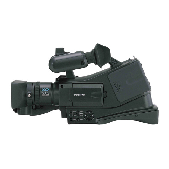
Panasonic AGDVC20P - 3 CCD DV CAMCORDER Kullanım Talimatları Kılavuzu - Sayfa 29
Video Kamera Panasonic AGDVC20P - 3 CCD DV CAMCORDER için çevrimiçi göz atın veya pdf Kullanım Talimatları Kılavuzu indirin. Panasonic AGDVC20P - 3 CCD DV CAMCORDER 42 sayfaları. Agmini-dv camera/recorder
Ayrıca Panasonic AGDVC20P - 3 CCD DV CAMCORDER için: Kullanım Talimatları Kılavuzu (40 sayfalar), Kullanım Talimatları Kılavuzu (42 sayfalar)

Using the DV Cable for Recording
(Digital Dubbing)
By connecting other digital video equipment with DV terminal
and the camera-recorder by using the DV cable (optional) 1,
high-image-quality dubbing can be done in digital format.
≥Set to Tape Playback Mode. (Player/recorder)
1
Connect the camera-recorder and digital video
equipment with the DV cable.
DV
1
DV
2
Set [ADVANCE] >> [REC STDBY] >> [YES]. (Recorder)
≥You do not have to follow this step when the remote control is
used in the digital dubbing.
3
Start playback. (Player)
4
Start recording. (Recorder)
Press the [3] button to select [¥/;] icon.
≥Or, without operating step 2
While pressing the [¥REC] button on the remote control,
press the [1] button.
V
/REW
STILL ADV
5
Press the [3] button to select the [¥/;] icon again or
press the [;] button on the remote control to stop
recording. (Recorder)
6
Stop playback. (Player)
T
¥
REC
A.DUB
W
PLAY
FF/
W
VOL
PAUSE
STILL ADV
STOP
Edit mode
You can connect a digital video unit equipped with a DV
connector and digitally transfer video and audio signals as well
as time code.
≥Before proceeding to connect or disconnect DV (IEEE1394)
cable, be absolutely sure to turn off the power of the units.
≥Before proceeding to connect the
unit which uses a 6-pin type DV
connector, carefully check the
shape of the DV (IEEE1394) cable
and the connectors on the DV
(IEEE1394) cable. Connecting a
connector upside down may
damage the parts inside the unit
and cause malfunctioning. Furthermore, connect the DV
(IEEE1394) cable to the unit which uses a 6-pin type DV
connector first.
≥When recording signals from an external unit, first check that
video signals are supplied.
≥While signals from an external unit are being recorded, do not
stop output on the external unit side or disconnect any of
cables. This may lead to a failure to recognize the signals
when you do recording again.
≥Do not apply force when connecting DV (IEEE1394) cable to
DV connector as this may damage the connector.
ª
To cancel the standby for recording
When the camera-recorder is standby for recording, press the
[4] button and select the [∫] icon.
≥Do not plug or unplug the DV cable during dubbing, or the
dubbing may not be completed properly.
≥If a picture (bilingual video, etc.) containing main sound and
sub sound has been dubbed, select the desired sound by
[SETUP] >> [AUDIO OUT] on playback.
≥Even if you use a device equipped with DV terminals such as
IEEE1394, you may not be able to perform digital dubbing in
some cases. For more information, see the instructions for
equipment connected.
≥Regardless of the menu settings on the recorder, digital
dubbing is carried out in the same mode as the [AUDIO REC]
mode of the playback tape.
≥The images on the recorder monitor may be disturbed, but it
does not affect the recorded images.
≥If a picture containing a copyright protection signal (copy
guard) is recorded by the camera-recorder, the picture is
distorted by mosaic-like patterns at playback.
≥When wide images are input, the display such as the menu
screen or the operation icon is expanded horizontally.
≥While pictures are input from the DV terminal, the operation
icon blinks on instead of appearing from the side of the screen
when you press the [ENTER] button.
4-pin
6-pin
type
type
29
