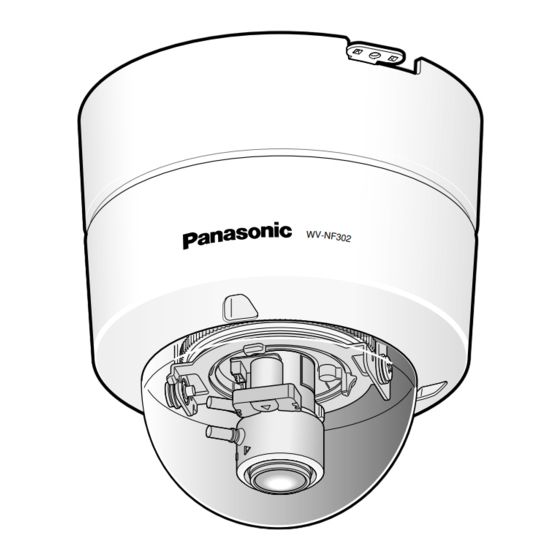
I Inside the dome cover
q Monitor out connector (for adjustment)
(RCA jack) [MONITOR]
This connector is provided only for
checking the adjustment the angular field
of view or the focus on the video monitor
when installing the camera or when serv-
icing. ( page 22)
w Indicators ON/OFF switch [LED]
Select "ON" or "OFF" to determine
whether or not to activate the link indica-
tor and the access indicator.
Important:
Select "ON" (default) for normal use.
When "ON" is selected, it is possible to
turn on/off this switch using a PC via a
network.
When it is necessary to turn off the indi-
cators, turn off the indicators using a PC
via a network (by selecting "OFF" for
"Link/Access LED" of "Basic Setup" on
the setup menu).
(Refer to the setup instructions (PDF) for
further information.)
e LEDs (Indicators)
The LEDs will light/blink according to the
status of the camera as follows.
Access indicator (green):
Blinks when the camera is accessed.
Link indicator (orange):
Lights when the communication with
a network is established.
SD memory card error indicator/Focus
assist indicator (red):
Lights in the following cases.
When images cannot be stored on
the SD memory card,
When the focus assist function is
started,
When BEST FOCUS is displayed.
r SD memory card slot [SD]
Insert an SD memory card. ( page 29)
t Focus assist (F.A.) button
Activates the focus assist function.
( page 27)
14
y Focus ring
Use this ring to adjust the focus.
( page 27)
u Zoom ring
Use this ring to adjust the angular field of
view. ( page 27)
i Tilting table
Rotate this table to adjust the tilting angle
of the camera. ( page 26)
o Image tilt adjustment ring
Use this ring to correct image tilt.
( page 26)
!0 Panning table fixing screw [LOCK]
Fix the panning table with this screw after
adjusting the panning angle of the cam-
era. ( page 26)
!1 Panning table
Rotate this table to adjust the panning
angle of the camera. ( page 26)
I Dome cover
Protect the camera head with this dome
cover.
!2 Upper cover
( pages 20 - 21)
!3 Smoke dome
Remove the cover film from the dome
cover after the installation is complete.
Do not touch the dome cover by hand
directly after removing the cover film.

