Digikeijs DR5033 Kullanım Kılavuzu - Sayfa 5
Genişletici Digikeijs DR5033 için çevrimiçi göz atın veya pdf Kullanım Kılavuzu indirin. Digikeijs DR5033 18 sayfaları. 3-ampere, h-bridge dcc booster
Ayrıca Digikeijs DR5033 için: Manuel (10 sayfalar), Kullanım Kılavuzu (18 sayfalar)

DR5033 DIGIBOOST
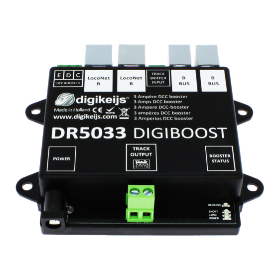
2.3 Hardware Overview
1 CDE Booster connec2on
(Please check whether the CDE connec2on of your control panel com-
plies with the requirements specified by Lenz®).
2 LocoNet® B Connector 1
3 LocoNet® B Connector 2
4 Tack Sniffer Input
By connec2ng the Track Sniffer input to the track output of the central unit, the track
signal is recognized even if none of the other input op2ons are available.
(CDE Booster connec2on, LocoNet® B, Roco® B Bus) can be used on the DR5033.
5 Roco® Booster Bus Connector 1
6 Roco® Booster Bus Connector 2
7
power supply
DC 15-19V 3,5A
8 Track Output
9 Booster Status LED
Track signal present (normal opera2on)
No track signal present.
(Loconet® B, B-Bus, CDE, Track Sniffer Input)
Booster load under 90%.
(LED becomes brighter under load)
Booster load greater than 90%.
Short circuit detected
Stop command detected (e.g. by the control unit)
Track Out reversed polarity.
Note:
If the blue LED lights up when driving over the booster separa2on
points, the track output of the DR5033 is connected with reversed polarity.
www.digikeijs.com
® R-Bus, B-Bus are trademarks which are registered in the name of Modelleisenbahn GmbH. XpressNet and RS-Bus is a trademark registered in the name of Lenz
Stand 2019-10-14
1
2
3
4
5
7
8
6
9
P 5
