Siemens SINAMICS G120 Hızlı Kurulum Kılavuzu

Endüstriyel Ekipmanlar Siemens SINAMICS G120 için çevrimiçi göz atın veya pdf Hızlı Kurulum Kılavuzu indirin. Siemens SINAMICS G120 2 sayfaları. Using blocksize converters in marine applications
Ayrıca Siemens SINAMICS G120 için: Başlarken (46 sayfalar), Kullanım Talimatları Kılavuzu (32 sayfalar), Başlarken (30 sayfalar), Donanım Kurulum Talimatları (2 sayfalar), Kurulum Talimatları ve Kullanım Kılavuzu (2 sayfalar), Kurulum Talimatları (2 sayfalar), Kurulum Talimatları (2 sayfalar), Kompakt Kullanım Talimatları (32 sayfalar), Manuel (42 sayfalar), Başlarken (50 sayfalar), Cihaz Kılavuzu (34 sayfalar), Uygulama Açıklaması (50 sayfalar), Kompakt Kullanım Talimatları (2 sayfalar), Manuel (31 sayfalar), Uygulama Kılavuzu (34 sayfalar), Kompakt Kullanım Talimatları (2 sayfalar), Kompakt Kullanım Talimatları (2 sayfalar)
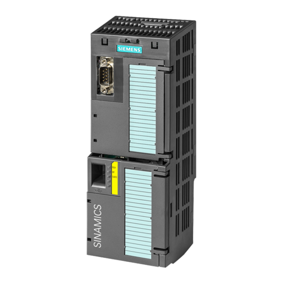
Siemens SINAMICS G120 Hızlı Kurulum Kılavuzu
SINAMICS
SINAMICS CONNECT
Quick Install Guide
1
Mounting
Before mounting and commissioning
1.1
IMPORTANT: observe all documents enclosed with the device and the
SINAMICS CONNECT Operating Instructions before mounting and
connecting the device.
Note that the term "device" refers to a SINAMICS CONNECT unit.
The symbol indicates that you can refer to the Operating
Instructions manual for more information.
1.2
Scope of delivery
Check the scope of delivery for completeness and intactness:
• One SINAMICS CONNECT device with one DC terminal block
mounted
• Quick Install Guide in English
1.3
Valid mounting orientation
50 °C
Horizontal
0 °C
When the device is used in the area of Industrial Control Equipment in
accordance with UL 61010-2-201, note that the device is classified as
"Open Type". A UL 61010-2-201 conform enclosure is therefore a
mandatory requirement for approval or operation according to UL
61010-2-201.
Free space required around the device
≥ 50 mm
≥ 50 mm
A5E45421417-002
10/2018
50 °C
Vertical
0 °C
≥ 50 mm
≥ 50 mm
1.4
Mounting
Mounting on DIN rails
1. Push the device down.
2. Swing the device from below.
3. Push the device to the rail.
Wall mounting
1. Guide a push-in lug
through the opening.
2. Press the push-in lug
down.
3. Drill the holes in the wall
and fasten the device to
the wall with screws and
anchors.
2
Commissioning
2.1
Connecting the power supply
The device must only be connected to a 9 V DC to 36 V DC power
supply which meets the requirements of safe extra low voltage (SELV)
according to IEC/EN/DIN EN/UL 60950-1.
The power supply must meet the requirements of NEC Class 2 or LPS
according to IEC/EN/DIN EN/UL 60950-1.
If there are voltage peaks on power supply lines, use a protective device
in the form of a varistor (MOV) UMOV = U-rated × 1.2 (BLITZDUCTOR
BVT AVD 24 (918 422) or compatible).
1
Power
9 V D
C
Off
t o 3 6
V D C
P o w e
r
S u p p
l y
1
2
1
2
3
+
2
3
3
Click