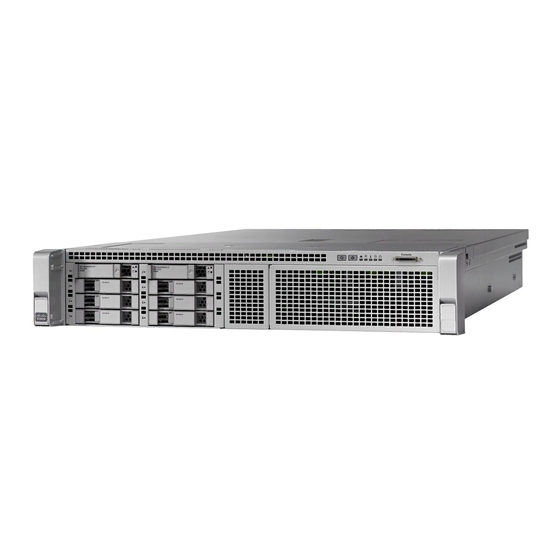
Cisco 8540 - Catalyst Campus Switch Router Modular Expansion Base Manuel - Sayfa 5
Ağ Donanımı Cisco 8540 - Catalyst Campus Switch Router Modular Expansion Base için çevrimiçi göz atın veya pdf Manuel indirin. Cisco 8540 - Catalyst Campus Switch Router Modular Expansion Base 11 sayfaları. Installing the controller
Ayrıca Cisco 8540 - Catalyst Campus Switch Router Modular Expansion Base için: Sorun Giderme Kılavuzu (23 sayfalar)

Installing the Controller
Installing the Controller In a Rack
Installing the Slide Rails
This section describes how to install the controller in a rack using the rack kits that are sold by Cisco.
Warning
To prevent bodily injury when mounting or servicing this unit in a rack, you must take special precautions to
ensure that the system remains stable. The following guidelines are provided to ensure your safety:
This unit should be mounted at the bottom of the rack if it is the only unit in the rack.
When mounting this unit in a partially filled rack, load the rack from the bottom to the top with the heaviest
component at the bottom of the rack.
If the rack is provided with stabilizing devices, install the stabilizers before mounting or servicing the unit in
the rack.
Statement 1006
Step 1
Attach the inner rails to the sides of the controller:
a) Align an inner rail with one side of the controller so that the three keyed slots in the rail align with the three pegs on
the side of the controller.
b) Set the keyed slots over the pegs, and then slide the rail toward the front to lock it in place on the pegs. The front slot
has a metal clip that locks over the front peg.
c) Install the second inner rail to the opposite side of the controller.
Figure 1: Attaching Inner Rail to Side of Controller
1
Step 2
Open the front securing plate on both slide-rail assemblies. The front end of the slide-rail assembly has a spring-loaded
securing plate that must be open before you can insert the mounting pegs into the rack-post holes.
On the outside of the assembly, push the green arrow button toward the rear to open the securing plate.
Front of controller
Installing the Controller In a Rack
2
Locking clip on inner rail
Installing the Controller
5
