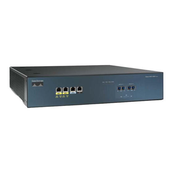
Cisco SCE 1000 and Hızlı Başlangıç Kılavuzu - Sayfa 30
Ağ Donanımı Cisco SCE 1000 and için çevrimiçi göz atın veya pdf Hızlı Başlangıç Kılavuzu indirin. Cisco SCE 1000 and 49 sayfaları. Service control engine 1000 2xgbe

Study the examples that follow to understand the procedure for various topologies.
Enter the topology configuration menu.
Step 1
Would you like to enter the Topology configuration menu? [no]: y
Enter your password if prompted.
–
Type y and press Enter.
The topology configuration dialog begins.
Step 2
Specify the connection mode.
To define inline connection mode, press Enter.
–
To define receive-only connection mode, type 2 and press Enter.
–
Enter Connection mode:
1- inline
2- receive-only
Enter your choice [1]:
Specify the On-failure link behavior.
Step 3
To specify Bypass, press Enter.
–
To specify Cutoff, type
–
Enter On-failure behavior:
1- bypass
2- cutoff
Enter your choice [1]:
Specify the admin status of the SCE 1000 after abnormal boot.
Step 4
To specify Not-Operational status after abnormal boot, press Enter.
–
To specify Operational status after abnormal boot, type
–
Enter admin status of the SCe after abnormal boot:
1- Operational
2- Not-Operational
Enter your choice [1]:
Examples
The following examples present the procedure for configuring the topology-related parameters for various topologies. Refer the
Setup Command Parameters, page 14 for a summary of appropriate values for the parameters for each topology.
• Example 1:, page 30
• Example 2:, page 31
• Example 3:, page 31
Example 1:
Following is a sample topology configuration for a topology using an external switch.
All other parameter values are automatically assigned by the system as follows:
• Link bypass mode on-failure — Bypass
• Admin status of the SCE after abnormal boot — Operational
Would you like to enter the Topology configuration menu? [no]: y
Enter Connection mode:
1- inline
2- receive-only
Enter your choice [1]: 2
30
and press Enter.
2
and press Enter.
1
