Alemite 9616-A Servis Kılavuzu - Sayfa 7
Su Pompası Alemite 9616-A için çevrimiçi göz atın veya pdf Servis Kılavuzu indirin. Alemite 9616-A 10 sayfaları. Low-pressure transfer pump
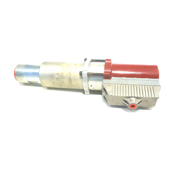
Low-Pressure Transfer Pump
Weep
Hole
Refer to Figure 2 Parts List
for Parts Identification
Figure 4 Pump Tube Assembly - Section View
Alemite Corporation
1-800-548-1191-http://[email protected]
13. Install O-Ring (25) onto the Stop.
5
14. Install and seat Spring Discs (32) in an alternate
6
pattern into Valve Body (34).
7
• See Figure 4 for details.
8
9
15. Install and seat O-Ring (30) into Seat (31).
16. Install the Seat assembly [O-Ring upward] into
11
the Valve Body.
10
18
17. Install Ball (29) into the Seat.
12
18. Install and seat O-Ring (33) onto the groove of
13
the valve Body.
14
19. Screw the Valve Body assembly onto the Stop.
15
• Tighten the Valve Body securely.
16
10
17
20. Install Air Motor Assembly (4)squarely onto the
27
Body.
19
• Use care passing the O-Ring.
20
21
• Make sure the outlet of the Body orients
22
5
21. Install the Cylinder assembly squarely onto the
26
bottom of the Outlet Body.
• Use care passing the O-Ring.
22. Install and seat Ring (27) [counter bore end
first] onto the Cylinder.
• Rotate the Ring until the holes align with the
23. Install Screws (28) that secure the Ring to the
Air Motor Assembly.
23
• Tighten the Screws evenly and securely in a
33
24
24. Screw Bushing (12) [with thread sealant] into
the Outlet Body.
• Tighten the Bushing securely.
25
30
29
Air Motor Assembly
31
32
25. Screw Shut-Off Valve (3) [with thread sealant]
34
into the Air Motor Assembly.
• Tighten the Shut-Off Valve securely in the
26. Screw Adapter (2) onto the Shut-Off Valve [with
thread sealant].
• Tighten the Adapter securely.
27. Install Air Coupler (1) onto the Adapter.
7
IMPORTANT: Make sure to press O-Ring
(30) fully into the groove of Seat (31).
properly with the inlet of the Air Motor.
Air Motor Assembly.
crisscross pattern.
position required.
SER 9616-A
Revision (10-98)