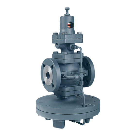
Armstrong GP-2000 Kurulum, Kullanım ve Bakım Kılavuzu - Sayfa 2
Kontrol Ünitesi Armstrong GP-2000 için çevrimiçi göz atın veya pdf Kurulum, Kullanım ve Bakım Kılavuzu indirin. Armstrong GP-2000 8 sayfaları. Pressure reducing valves
Ayrıca Armstrong GP-2000 için: Manuel (8 sayfalar), Manuel (2 sayfalar)

Improper sizing or adjustment of the pressure reducing valve may cause hunting, scale problems, water hammer, etc.
and can heavily damage the main parts of the valve. Adjust the valve as follows:
1. Close the gate valves before and after the pressure
reducing valve and blow fluid leisurely through the by-
pass line. Adjusting the opening of the by-pass globe
valve so as not to blow the safety relief valve. After
draining, be sure to close the by-pass globe valve.
2. Loosen the lock nut and adjusting screw to relieve the
pressure on the adjusting spring.
3. Slowly open the inlet side gate valve to the full open
position, and open the outlet side gate valve enough
so that a little fluid can flow through.
4. Slowly turn the adjusting screw clockwise until the
desired pressure is obtained while watching the
pressure gauge at the outlet side.
Note: Before disassembly, check to make sure that the valves before and after the reducing valve are closed, including
the valve in the control pipe. Also, make sure that the pressure has been relieved and that the valves are holding.
A. Disassembly of the Pilot Valve
Ref: (Fig. 3-1)
1. Loosen the (28) lock nut, turn the adjusting screw (27)
counterclockwise and turn until pressure is relieved
from spring.
2. Remove the hex head bolts (37) and take out the top
spring plate (25), adjusting spring (24), bottom plate
(26) and two (2) pilot diaphragms (23). (1 diaphragm if
1.5-3 spring)
3. Remove the (18) pilot valve capsule [hexagonal part at
the center of the (2) pilot body. Disassemble pilot valve
capsule ñ place a 7/32î socket over small hexagonal
screw in middle of capsule (21) and hold opposite end
with a flat head screwdriver. Turn counterclockwise to
unscrew and expose valve stem and seat.
B. Disassembly of the Main Valve
1. Disconnect the copper tubing on the side of the valve
(30A), (30B), and (30C).
1. Check to make sure there are no scratches on the
main valve, valve seat or pilot valve. If there are no
scratches apply lapping compound and re-lap the valve
and seat. (See Bulletin AY-768).
2. Make sure the sliding parts (Pilot valve stem and main
valve stem) move freely.
3. Never-Seeze
gasket compound should be used on
Æ
both main diaphragms and on bottom of pilot dia-
phragms.
Start-Up and Adjustment Procedures
Disassembly
Assembly
5. Slowly open the outlet side valve to the full open
position.
6. After adjustment, tighten the lock nut.
Note: Downstream usage must be present in order to set
any pressure-reducing valve.
Table 2-1. Spring Chart
Reduced Pressure
*1.5 - 3 psig
3 - 21 psig
15 - 200 psig
*When using this spring range, remove one (1) pilot diaphragm.
Capacities are reduced by 1/2 when this spring is being used.
2. Remove the four hex head bolts (38) from the pilot
body (2) to remove the pilot from the main body (1). If
the pilot is mounted remotely, remove the bolts to the
main valve top cover. Care should be taken when doing
this ñ the main valve is held by a spring, which is
compressed. Once bodies are apart, remove spring
plate retainer (14), screen (15), main valve spring (13)
and main valve (6).
3. If the seat must be replaced, remove the four nuts (40)
that attach the main body (1) to the top diaphragm
case. The main valve seat is tightened from the bottom
side of the body using a ìTî bar. Loosen with ìTî bar
and unscrew main valve seat from the top.
C. Disassembly of the Main Diaphragm
1. Remove all bolts (41) holding the top and bottom
diaphragm cases (4 & 5) together.
2. Separate both halves. Remove both main diaphragms
(12), retainer (11) and main spindle (9).
4. Assemble valve in reverse order from disassembly.
5. Tighten bolts uniformly (criss-cross pattern).
6. Verify if your valve has old or new type tubing to assure
proper placement of orifices (see page 6).
7. Be sure fitting 30A, 30B, 30C and tee fitting (33) are in
the correct position and not over tightened.
Ref. Figure 6-1.
8. Make sure copper pilot valve gasket (22) and main
valve seat gasket (8) are in place before tightening pilot
valve capsule and main valve seat.
2
Color Code
Yellow
Yellow
Green
