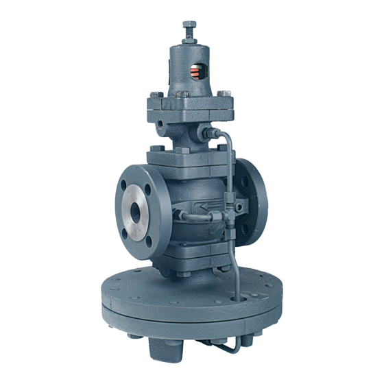
Armstrong GP-2000 Kurulum, Kullanım ve Bakım Kılavuzu - Sayfa 5
Kontrol Ünitesi Armstrong GP-2000 için çevrimiçi göz atın veya pdf Kurulum, Kullanım ve Bakım Kılavuzu indirin. Armstrong GP-2000 8 sayfaları. Pressure reducing valves
Ayrıca Armstrong GP-2000 için: Manuel (8 sayfalar), Manuel (2 sayfalar)

Remote Mount Pilot Tubing ñ Assembly Instructions
1. The valves have the following ìsimilarî parts. ºî long
nipple (4), ºîx ºî short nipple (6), fitting B (13) and
union set (5). Use thread tape on the threads of both
nipples.
2. Remove the ºî plug on the inlet side of the main valve
body (1) (for GP-2000 remote mount pilot and OB-2000
temperature pilot) with an allen wrench.
3. Thread the ºî long nipple (4) into the main valve body
(1) (in place of the ºî plug).
4. Thread one-half of the union set (5) onto the long
nipple (4). Thread the other half onto the short nipple
(6).
5. Thread the short nipple (6) into the pilot (2) or (3).
Note: The arrow on the side on the temperature
pilot (3) must point away from the main valve.
The short nipple (6) will thread into the bottom
cap of the pressure pilot (2) (remote mount).
6. Assemble the C-tube (8), B-tube (7) and tee (12) as
shown in the diagrams on Page 6. Connect the union
set (5) and tighten. Very Important: Be sure that the
groove on the Tee is on the top (Old GP-11 series
does not have groove and can be used either
way.
For GP-2000 Remote Mounted Pilot
7. Place fitting A (14) into the pilot and thread into place.
Note: This fitting is open with no restricted open-
ing. Use thread tape on threads.
8. Once the union set (5) has been tightened to fitting A
(14) of the pressure pilot (2) it should be facing the
main valve (1). (See remote mount drawing)
9. Connect the S shaped D-tube (9) to the outlet of the
pressure pilot at fitting A (14) and to top of the tee (12)
and tighten. Note: make sure the downstream
sensing port (15) on the pilot faces downstream.
For OB-2000
10. Thread the elbow (10) into the outlet of the temperature
pilot (3) and into the bottom of the main valve as
shown in drawings.
11. Place the D-tube (9) into the elbow (10) and the tee
(12) and tighten.
OB-2000 & GP-2000, K1, K3, K6
(See drawings for proper piping of remote pilots)
6
1
5
4
10
GP-2000, GP-2000K-1,
GP-2000K-3, GP-2000K-6
Remote Mount
1 Main Valve Body
2 Pressure Pilot or Air Pilot (not shown)
3 Temperature Pilot
4 1/4î Long Nipple
5 Union Set
6 1/4î x 1/4î Short Nipple
7 B-Tube
8 C-Tube
9 D-Tube
10 Elbow
11 Capillary
12 Tee
13 Fitting B
14 Fitting A
15 Downstream Sensing Port
1
5
6
4
8
10
5
2
14
9
15
13
8
7
10
3
9
13
10
7
12
11
10
OB-2000
12
