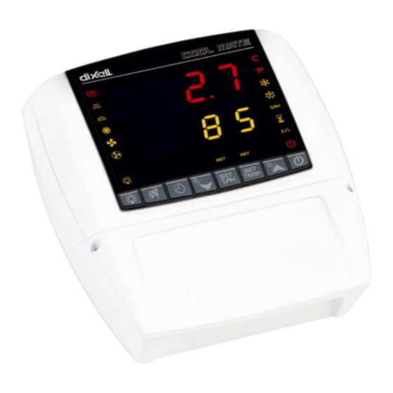
dixell COOL MATE XLH360 Kullanım Talimatları Kılavuzu - Sayfa 9
Sıcaklık Kontrolörü dixell COOL MATE XLH360 için çevrimiçi göz atın veya pdf Kullanım Talimatları Kılavuzu indirin. dixell COOL MATE XLH360 16 sayfaları. Cool mate temperature and humidity controller for seasoning-maturing cabinets

dIXEL
trC=cLE at the end of the stopping phase the regulation restarts from the running phase.
DEFROST
tdF
Defrost type: rE = electrical heater (Compressor OFF); in = hot gas (Compressor and defrost relays ON)
EdF
Defrost mode:
in = interval mode. The defrost starts when the time "Idf" is expired; Sd=Smartfrost mode. The IdF time (interval
between defrosts) is increased only when the compressor is running (even non consecutively).
SdF
Set point for SMARTFROST: (-30
SMARTFROST mode.
dtE
Defrost termination temperature: (-50,0÷110,0°C; -58÷230°F) (Enabled only when the evaporator probe is present) sets the
temperature measured by the evaporator probe which causes the end of defrost.
IdF
Interval between defrosts: (1÷120h) Determines the time interval between the beginning of two defrost cycles.
MdF
Duration of defrost: (0÷255 min) When P2P = n, no evaporator probe, it sets the defrost duration, when P2P = y, defrost end based on
temperature, it sets the maximum length for defrost.
dFd
Display during defrost: rt = real temperature; it = temperature reading at the defrost start;
Set
set point; dEF = "dEF" label; dEG = "dEG" label;
dAd
Defrost display time out: (0
255 min) Sets the maximum time between the end of defrost and the restarting of the real room temperature
÷
display.
Fdt
Drain down time: (0÷60 min.) time interval between reaching defrost termination temperature and the restoring of the control's normal
operation. This time allows the evaporator to eliminate water drops that might have formed due to defrost.
dPO
First defrost after start-up: y = Immediately; n = after the IdF time
Hud
Humidity control during defrost: no: the humidity control is stopped during the defrost; yES the humidity control works also during the
defrost.
FANS
FnC
Fan operating mode: C-n = running when a load is on, OFF during the defrost; C-y = running when a load is on, ON during the defrost;
O-n = continuous mode, OFF during the defrost; O-y = continuous mode, ON during the defrost;
EXTRACTOR FANS
rFi
Interval between 2 cycles of change of air (0÷120 ore; 0 = only manual starting)
rFd
Duration of change of air cycle (0÷250min; 0 = only manual stopping)
TEMPERATURE ALARMS
ALC
Temperature alarm configuration: rE = High and Low alarms related to Set Point; Ab = High and low alarms related to the absolute
temperature.
ALL
Low temperature alarm setting: ALC = rE , 0
and after the ALd delay time, the LA alarm is enabled,.
ALU
High temperature alarm setting: ALC= rE, 0
after the ALd delay time the HA alarm is enabled.
ALH
Temperature alarm recovery differential: (0,1÷25,5°C; 1÷45°F) Intervention differential for recovery of temperature alarm.
ALd
Temperature alarm delay: (0÷255 min) time interval between the detection of an alarm condition and the corresponding alarm signalling.
dAO
Delay of temperature alarm at start-up: (0min÷23h 50min) time interval between the detection of the temperature alarm condition after
the instrument power on and the alarm signalling.
EdA
Alarm delay at the end of defrost: (0
defrost and the alarm signalling.
dot
Delay of temperature alarm after closing the door : (0
door.
HUMIDITY ALARMS
AHC
Humidity alarm configuration: rE = High and Low alarms related to humidity Set Point ; Ab= High and low alarms related to the
"absolute" humidity.
AHL
Low humidity alarm setting: (with AHC = rE: 0 ÷ 50. With AHC = Ab: Lci ÷ AHu)
when this humidity is reached and after the AHd delay time, the HLA alarm is enabled,.
AHu
High humidity alarm setting: (with AHC = rE: 0÷50°C. with AHC = Ab: AHL ÷ uci
when this humidity is reached and after the AHd delay time the HHA alarm is enabled.
AHH
Humidity alarm recovery differential: (0.5÷20.0) Intervention differential for recovery of humidity alarm.
AHd
Humidity alarm delay: (0÷255 min) time interval between the detection of an alarm condition and the corresponding alarm signalling.
dHo
Delay of humidity alarm at start-up: (0min÷23h 50min) time interval between the detection of the humidity alarm condition after the
instrument power on and the alarm signalling.
doH
Alarm delay at the end of defrost: (0
and the alarm signalling.
doA
Open door alarm delay:(0÷255 min) delay between the detection of the open door condition and its alarm signalling: the flashing
message "dA" is displayed.
tbA
Alarm relay status after pushing a key: on= the relay remains on; off= the relay is switched off.
nPS
Pressure switch number: (0
15) Number of activation of the pressure switch, during the "did" interval, before signalling the alarm event
÷
(I1F= PAL). If the nPS activation in the "did" time is reached, switch off and on the instrument to restart normal regulation.
1592017410 XLH360 GB r1.0 15.04.2005.doc
Operating Instructions
30 °C/ -22
86 °F) evaporator temperature which allows the IdF counting (interval between defrosts) in
÷
÷
50 °C or 90°F; ALC = Ab , - 50°C or -58°F
÷
50°C or 90°F; ALC= Ab, ALL
÷
255 min) Time interval between the detection of the temperature alarm condition at the end of
÷
255 min) Time delay to signal the temperature alarm condition after closing the
÷
÷
255 min) Time interval between the detection of the humidity alarm condition at the end of defrost
XLH360
cod. 1592017410
ALU; when this temperature is reached
÷
110°C or 230°F; when this temperature is reached and
÷
9/16
