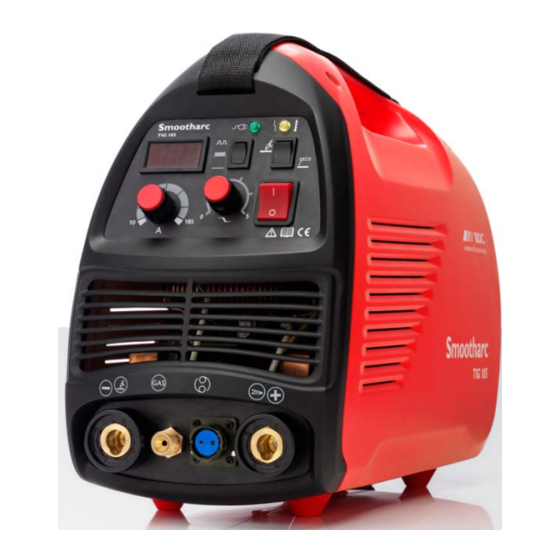
BOC Smootharc TIG 185 DC Посібник з експлуатації - Сторінка 16
Переглянути онлайн або завантажити pdf Посібник з експлуатації для Зварювальна система BOC Smootharc TIG 185 DC. BOC Smootharc TIG 185 DC 19 сторінок. Boc smootharc tig 185 dc welder
Також для BOC Smootharc TIG 185 DC: Посібник з експлуатації (15 сторінок)

16
BOC Smootharc TIG 185 DC Service manual
2.0 T roubleshooting and maintenance
Problem
1 P ress the power switch,
power indicator, meter, and
fans with no data, press the
torch without response.
2 P ress the power switch, the
power indicator and meter is
ok, the fan is abnormal, the
machine has no response
when pressing the switch.
3 P ress the power switch,
power indicator, meter, and
fan works normally. Press the
switch of the torch without
response.
4 T urn on the machine
normally, without high
frequency
5 T urn on the machine
normally, the abnormal
indicator is on.
6 T urn on the machine
normally, could start arc, but
the weld appears black.
7 T he welding current is
unstable, uncontrollable.
8 S kip after turning on the
machine.
9 T he high frequency could not
stop.
Possible Reasons
1 C heck the circuit is normal, and external power supply (AC240) is OK.
2 C heck the power cable, switch, and connector is tightly connected, use a multi-meter
to test the plug (PZ01-005-O1 CON10) for DC340V±5V.
1 C heck the inverter board has DC24V output, use a multi-meter to test the CON4's
PM01-001-E12 pin 1 and 2. If it has 24V output, test other areas.
2 S tart relay K1 on bottom board does not respond properly (it can be indicated by the
solenoid valve jumping).
3 S tart relay K2 in power circuit does not respond properly, check optical U1, MOSFET
Z24 (Q4) resistor RV1, and whether the relay is damaged or not.
4 P ressing the power button continuously in a short time, results in the field-discharge
resistance becoming overheated P ower off the machine for several minutes.
1 S witch of the torch or the cable is loose.
2 Gas socket is loose or the cable is broken.
1 P ull off the high frequency cable(PM01-001-E12 CON2), use a multi-meter to test
the output for DC230. If yes and could start arc, check the starting arc under high
frequency.
a) C heck whether the high frequency cable connection to the bottom board
(PZ01-005-O1 CON4) and cable for arc start is not loose.
b) C heck if the high voltage discharge nozzle is connected correctly, or the surface is
oxidized.
c) C heck if the high voltage components (D3-D6), high voltage output capacitors
(C7, C10, C11) are not damaged.
d) C heck the high frequency relay on the bottom board is responding properly.
2 C heck for the DC230 output, possibly the inverter circuit is abnormal.
a) C heck if the control module, has output for the drive signal or works normally.
b) C heck if the inverter and main current cable is not loose PM01-001-E12 CON1 .
1 T he over-heat protection is activated, turn off the machine, and could restart the
machine successfully while the power indicator is off.
2 T he over-heat protection works, the machine will be ok after 2-3 minutes.
3 T he inverter circuit and start arc is abnormal, turn off the machine and pull off
the plug of the high frequency start arc power in PM01-001-E12, then turn on the
machine and press the switch.
a) I f the abnormal indicator does not go on, the transformer T1 on the PZ01-005-O1
or D3-D6 is damaged.
b) I f the abnormal indicator is on, then pull off the plug CON1 for power supply
in the PM01-001-E12 If the light is still on, some of the MOSFET components
are damaged. If the light goes off, the rectifier pipe on PZ01-005-O1 or the
transformer is damaged.
c) C heck if the feedback circuit is open-circuit, check the feedback cable is properly
connected.
1 C heck if the solenoid valve is jammed or damaged.
2 T he solenoid valve relay (PZ01-005-W K1) is damaged.
3 C heck the torch for wear or damage.
4 T ungsten electrode is in poor condition, or the shielding gas is incorrect.
1 T he potentiometer is loose or damaged.
2 F iltering capacitor PZ01-005-O1 in the bottom board is leaking or damaged.
3 T he welding cable is too long and thin resulting in the unstable current.
1 T he rectifier silicon bridge is damaged.
2 T he power cable is short-circuited.
1 H igh frequency relay (PZ01-005-W K3) is damaged.
2 T he output voltage disturbs the voltage.
Ver.1 Rev.1 . 0314
Solution
1 C heck the external power
supply.
2 C heck the connector.
1 C heck and remove.
2 C heck and remove.
3 C heck and remove.
4 T urn off the machine for
several minutes.
1 C heck and remove.
2 C heck and remove.
1 C heck and replace.
2 C heck and replace.
1 T he machine will be ok after
turning off the machine for
five minutes.
2 S top the machine for a while.
3 C heck and remove.
1 C lean.
2 C heck and replace if
necessary.
3 C heck and replace if
necessary.
4 R eplace.
1 C heck and remove.
2 C heck and remove.
3 I ncrease the cross section of
the cable.
1 C heck and replace.
2 R eplace.
1 C heck and remove.
2 A dd capacitor between
output and ground.
