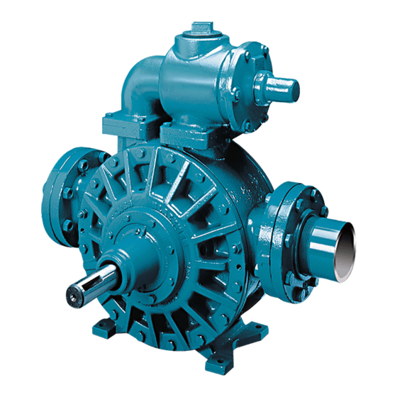
Dover PSG BLACKMER MRLN4B Інструкції з монтажу, експлуатації та технічного обслуговування - Сторінка 10
Переглянути онлайн або завантажити pdf Інструкції з монтажу, експлуатації та технічного обслуговування для Водяний насос Dover PSG BLACKMER MRLN4B. Dover PSG BLACKMER MRLN4B 20 сторінок. Power pumps

MAINTENANCE: M(R)LX(W)4B Series
8.
MECHANICAL SEAL
Rotating Assembly
a.
Make sure the shaft is free of burrs that might cut or
nick the O-rings. Put a light film of grease on the
shaft between the rotor and the shaft threads to
facilitate seal installation.
b.
Slide the mechanical seal rotating assembly (153B &
153E) over the shaft with the drive tangs of the
jacket towards the rotor, and the polished face
outward.
c.
Rotate the jacket assembly to engage the drive
tangs into the rotor slots. IMPORTANT: Failure to
engage the drive tangs of the jacket assembly will
cause seal damage when the hub is attached.
d.
Clean the rotating seal face with a clean tissue and
alcohol.
Stationary Seat
a.
Put a light coating of grease in the seal recess of the
hub.
b.
Align the locating pin in the stationary seat (153A)
with the slot in the bottom of the hub recess.
c.
Insert the stationary seat (153A) and O-ring (153D)
into the seal recess with the polished face outward.
d.
Clean the polished face with a clean tissue and
alcohol. Bronze seal faces should be oiled during
installation, but other seal faces must be kept clean
and dry. Note: Carbon/PTFE rotating seal face
(153B) is installed as a one-piece assembly.
9.
HUB ASSEMBLY
a.
Before installing the second hub assembly, grease
the three (3) head chamfers.
b.
Install the hub O-rings (72A & 72B), and slide the
hub onto the shaft with the V-notch of the hub
towards the bottom of the pump. Use extreme care
to avoid damage to the seal face.
c.
Install and hand tighten the two hub capscrews
(21D) to pull the hub into place.
10. BEARING AND BEARING SPACER
a.
Hand pack the bearing (24) with grease. See
LUBRICATION section of this manual.
b.
Insert the greased bearing (24) into the bearing
housing of the hub. Tap the outer edge of the
bearing to ensure that it is properly seated.
c.
Slide the bearing spacer (24D) onto the shaft.
11. Return to the first head assembly and remove and
reassemble the hub, this time including the mechanical
seal and O-rings (see Step 8 for mechanical seal
instructions). Lightly grease the shaft and the head
chamfers before installing the assembly to enable the O-
rings to slide into place without damage. Reinstall the
bearing spacer (24D).
12. LOCKNUT INSTALLATION
The bearing locknuts (24A) and lockwashers (24B) MUST be
installed and adjusted properly. Overtightening locknuts can
cause bearing failure or a broken lockwasher tang. Loose
locknuts will allow (See Figure 8) the rotor to shift against the
heads, causing wear.
a. On both ends of the pump shaft, Install a lockwasher
(24B) with the tangs facing outward, followed by a
locknut (24A) with the tapered end inward. Ensure the
inner tang "A" of the lockwasher is located in the slot
in the shaft threads, bending it slightly, if necessary.
b. Tap outer edge of bearings (24) with soft mallet to
ensure they are bottomed in the head recess. Tighten
both locknuts (24A). DO NOT overtighten and bend or
shear the lockwasher inner tang.
c. Loosen both locknuts (24A) one complete turn.
d. Tighten one locknut (24A) until a slight rotor drag is felt
when turning the shaft by hand.
e. Back off the nut the width of one lockwasher tang "B".
Secure the nut by bending the closest aligned
lockwasher tang into the slot in the locknut. The pump
must turn freely when rotated by hand.
f. Tighten the opposite locknut (24A) by hand until it is
snug against the bearing (24). Then, using a spanner
wrench, tighten the nut the width of one lockwasher
tang. Tighten just past the desired tang, then back off
the nut to align the tang with the locknut slot. Secure
the nut by bending the aligned lockwasher tang into
the slot in the locknut. The pump must continue to turn
freely when rotated by hand.
g. To check adjustment, grasp the nut and washer with
fingers and rotate back and forth. If this cannot be
done, one or both locknuts are too tight. Alternately
loosen one stop at a time .001" (.025mm) until
properly adjusted. Begin by loosening the locknut
adjusted last.
h. After adjustment is complete, remove the bearing
cover capscrews and 3/8" washers from both ends of
the pump.
106-A00
Page 10/20
Figure 8 Locknut Adjustment
