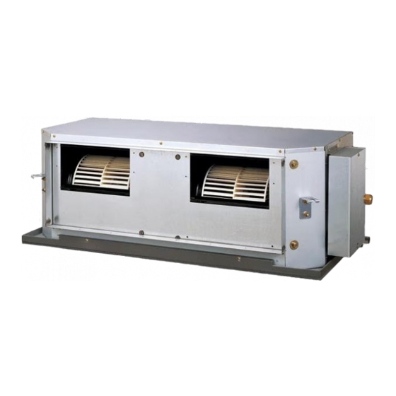
AirStage ARUH48RLAV Посібник з монтажу - Сторінка 12
Переглянути онлайн або завантажити pdf Посібник з монтажу для Кондиціонер AirStage ARUH48RLAV. AirStage ARUH48RLAV 15 сторінок. Indoor unit (duct type)

(3) Connection methods
• Wire modifi cation
Remove insulation from wire attached to wire kit connector.
Remove insulation from fi eld supplied cable. Use crimp type insulated butt connector to
join fi eld cable and wire kit wire.
Connect the wire with connecting wire with solder.
Important: Be sure to insulate the connection between the wires..
Field supply
• Connection terminals
Controller PCB
Output
terminal
(CN24)
• Wiring arrangement
Controller PCB
Binder clamp
Connecting
cable(s)
En-11
Option parts
External input/output wire
Insulated connection
Output
Output
terminal
terminal
(CN23)
(CN22)
Input
terminal
(CN27)
Cable
clamp
Binder
(Field supply)
6.6. Remote sensor (Optional parts)
For the installation method, please refer to the INSTALLATION MANUAL of remote sensor.
Connection methods
• Connection terminals
Controller PCB
• Wiring arrangement
Controller PCB
Earth (Ground)
screw
Connecting
cable(s)
• Remove the existing connector and replace it with the remote sensor connector (ensure
that the correct connector is used).
• The original connector should be insulated to ensure that it does not come into contact
with other electrical circuitry.
• Use conduit hole when external output cable is used.
Setting for room temperature correction
When a remote sensor is connected, set the function setting of indoor unit as indicated
below.
• Function Number "30":
Set the Setting Number to "00". (Default)
• Function Number "31":
Set the Setting Number to "02".
* Refer to "7.3. Function setting" for details about Function
Number and Setting Number.
Remote sensor
terminal (CN19)
Shield wire
Cable
clamp
Binder clamp
Binder
(Field supply)
