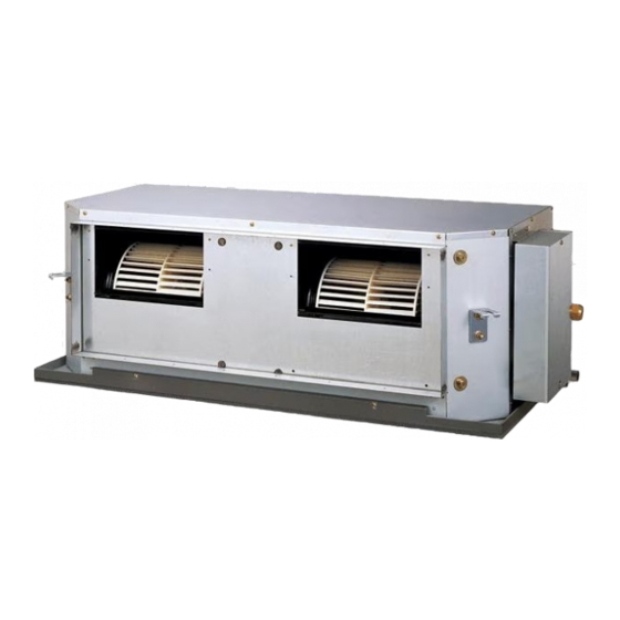
AirStage ARUH48RLAV Посібник з монтажу - Сторінка 10
Переглянути онлайн або завантажити pdf Посібник з монтажу для Кондиціонер AirStage ARUH48RLAV. AirStage ARUH48RLAV 15 сторінок. Indoor unit (duct type)

(2) After wiring is complete, clamp the remote controller cable, transmission cable and
power supply cable with binder.
For U.S.A. and Canada
For Others
When installing a screw on the terminal block, do not cut the cable by overtightening
the screw. On the other hand, an under tightened screw can cause faulty contact,
which will lead to a communication failure.
(3) Attach the control box cover.
En-9
Binder (Medium)
(Accessories)
Remote controller cable
Y1: Red
Y2: White
Y3: Black
X1, X2:
Transmission cable
GND
Conduit
(L1, L2 (N): Power supply
Lock nut
cable)
Binder (Medium)
(Accessories)
Remote controller
cable
Y1: Red
Y2: White
Y3: Black
X1, X2: Transmission
cable
Binder (Medium)
(Accessories)
Grommet edging
(Accessories)
L1, L2 (N): Power supply cable
CAUTION
] 1
6.5. External input and external output (Optional parts)
Controller PCB
Output
terminal
(CN24)
(1) External input terminals
• Indoor unit can be Start/Stop or Emergency stop by using indoor unit PCB CN27.
Wiring methods and specifi cations
• A twisted pair cable (22AWG) should be used. Maximum length of cable is 82 ft. (25 m)
• Use an external input and output cable with appropriate external dimension, depending
on the number of cables to be installed.
• The wire connection should be separate from the power cable line.
• Open circuit voltage : ≤ 5.25 (V).
• Short circuit current : ≤ 0.6 (mA).
• Short circuit detection resistance (R ON) : ≤ 500 (ohm).
• Short circuit detection resistance (R OFF) : ≥ 100 (kilo-ohm).
*
*
Ch 2
Ch 1
Connected unit
* Select very low current use contacts (usable at DC12V, DC1mA or less).
When connected to no voltage terminals of multiple indoor units with a connected unit,
insulate each indoor unit with relay, etc. as shown on below example.
When connected to multiple indoor units directly, it will cause breakdown.
Input device 1
Input device 2
Output
Output
terminal
terminal
(CN23)
(CN22)
Input
terminal
(CN27)
P.C.B
1
2
3
GND
P.C.B
K1
K4
CN27
P.C.B
K2
K5
CN27
P.C.B
K3
K6
CN27
K1-K6: Relay
(Device for DC Current)
CN27
